Code
library(ggspectra)
library(photobiologyLEDs)
library(photobiologyWavebands)A first attempt at spectral imaging with a mirroless camera and multichannel LED arrays with six and ten colours of LEDs.
LED light
Hyperspectral and spectral cameras are used in plant research, crop breeding and in commercial farming, both in the field with drones and in controlled environments. The main limitation to their widespread use is cost.
Traditional spectral cameras have a monochromator and scan the image line by line (see Specim’s, Resonon’s, and other similar cameras). Some “snapshot” spectral cameras are based on a normal CMOS image sensor with a special filter or filter plus microlenses (see Cubert’s cameras). In both cases the image resolution is relatively low and the cost of cameras very high. These cameras in most cases are not able to “see” ultraviolet radiation. However, they do have good wavelength resolution (up to 2 to 3 nm, and .
The cameras described above depend on discriminating different wavelengths at the camera. A recent commercial camera uses single colour LEDs to obtain spectral images, however, even if using a very simple and cheap camera module its price is very high (see RAYN Vision System Camera). Using monochromatic light to measure reflectance or transmittance is not a new approach in that it is frequently used in spectrophotometers where the monochromator is at the light source.
These two approaches are not fully equivalent as they detect fluorescence differently.
Because of this I decided to try the colour-LED-based approach with a good photographic camera and also test performance in the ultraviolet with a full-spectrum converted photographic camera. Below I describe some of these tests.
I used an Olympus O-M1 digital mirrorless camera. This camera has a 20 Mpix sensor. It can take both 20 Mpix images and 80 Mpix images. In the later case using sensor shift and in-camera image merging.
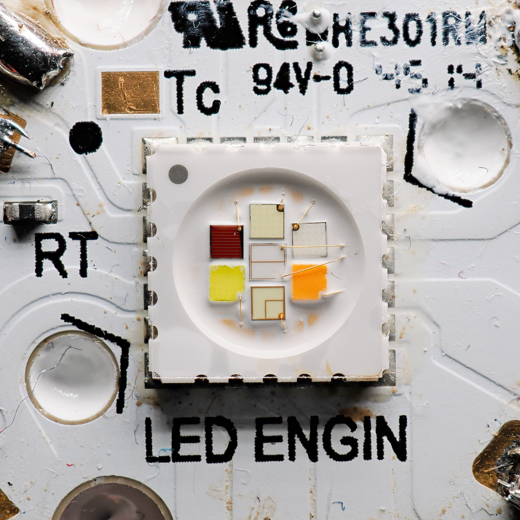
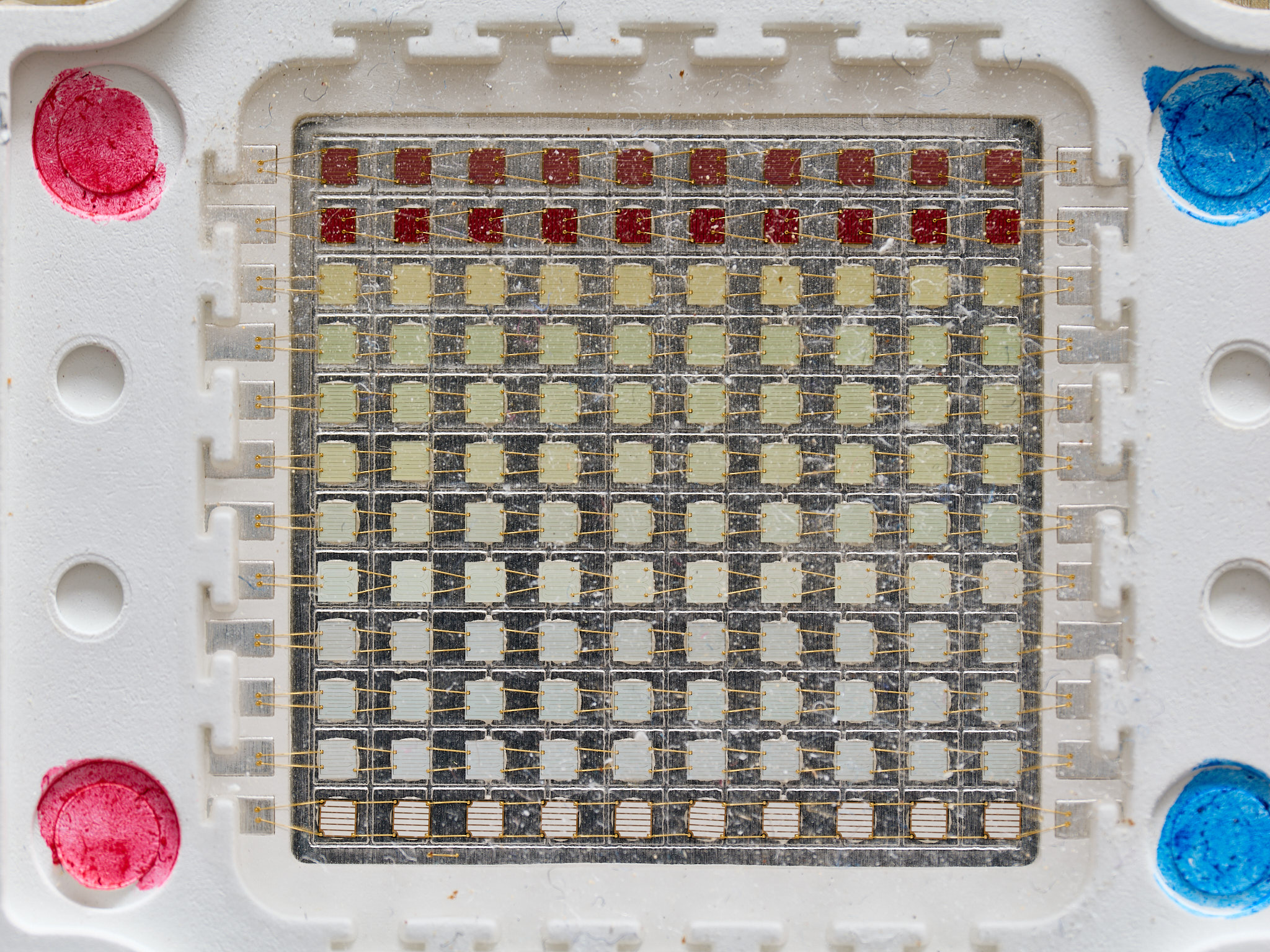
Ledengin Osram LZ7-N4M100 7-channel LED array from 2018 or so: six colours + white. Max 20 W total. It has a flat glass window protecting the chips. LES 3.8 mm (all chips are within a 3.8 mm diameter area (Figure 1). Maximum rated current per channel is 700 mA. For the photographs below current was set to 350 mA, the maximum for the driver used.
library(ggspectra)
library(photobiologyLEDs)
library(photobiologyWavebands)Of the seven channels, six are “single colour” (Figure 2) and one is white (Figure 3).
colour_channels <-
  grepl("LZ7", names(leds.mspct)) & !grepl("white", names(leds.mspct))
autoplot(leds.mspct[colour_channels],
         range = c(300, 750),
         geom = "spct",
         w.band = VIS_bands()) +
  theme_bw() + theme(legend.position = "none")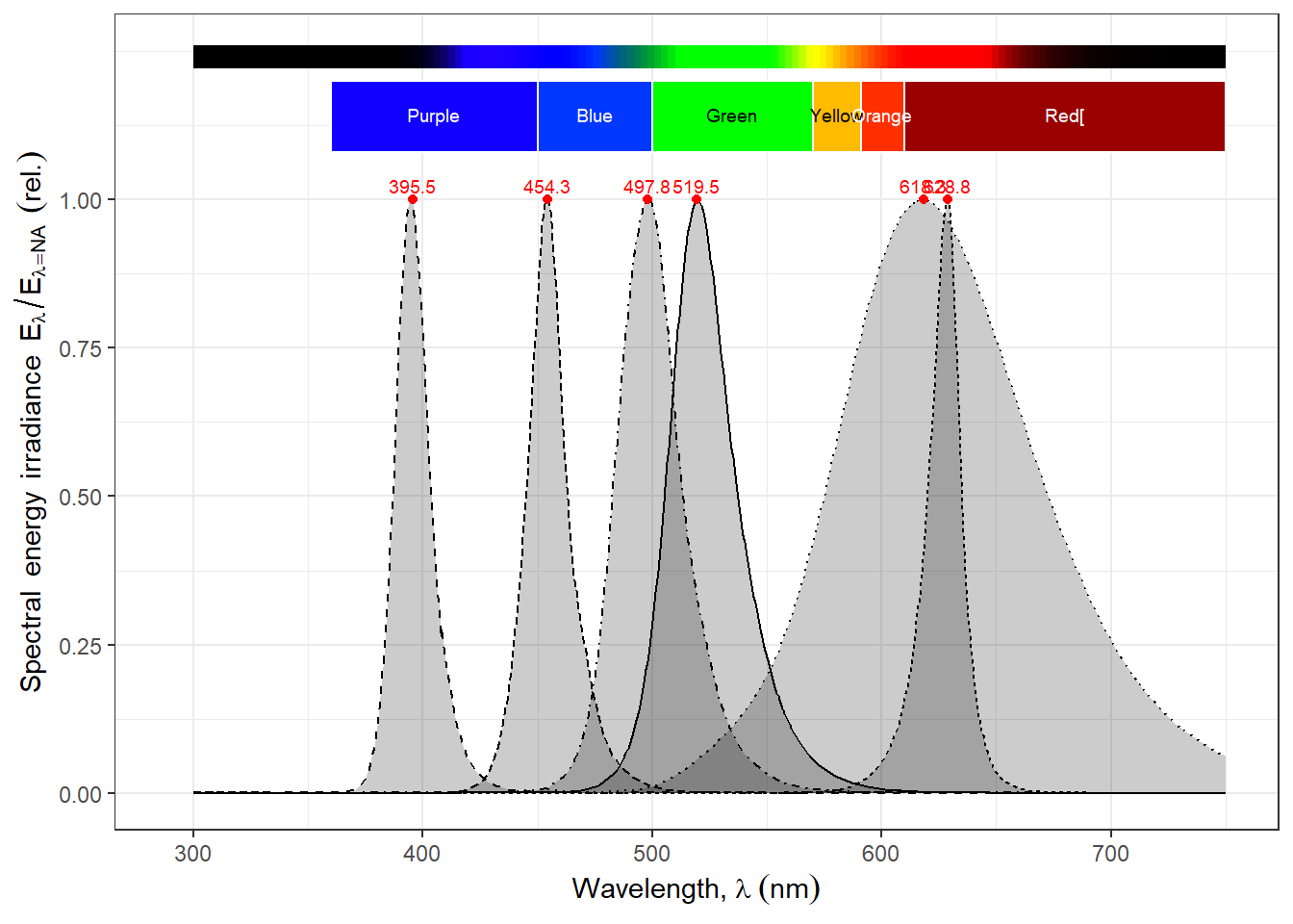
white_channel <-
  grepl("LZ7", names(leds.mspct)) & grepl("white", names(leds.mspct))
autoplot(leds.mspct[white_channel],
         range = c(350, 850),
         geom = "spct",
         w.band = VIS_bands()) +
  theme_bw() + theme(legend.position = "none")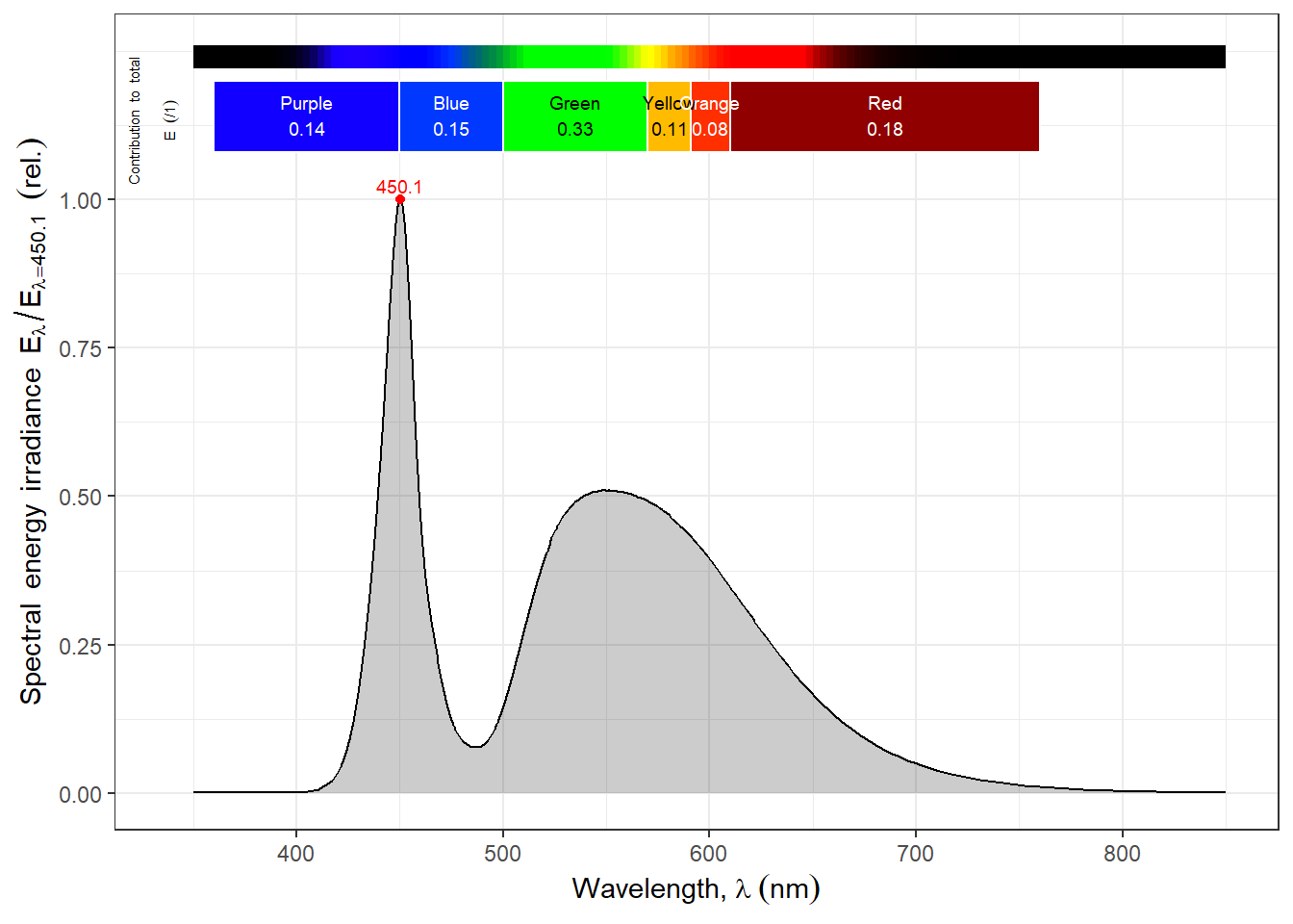
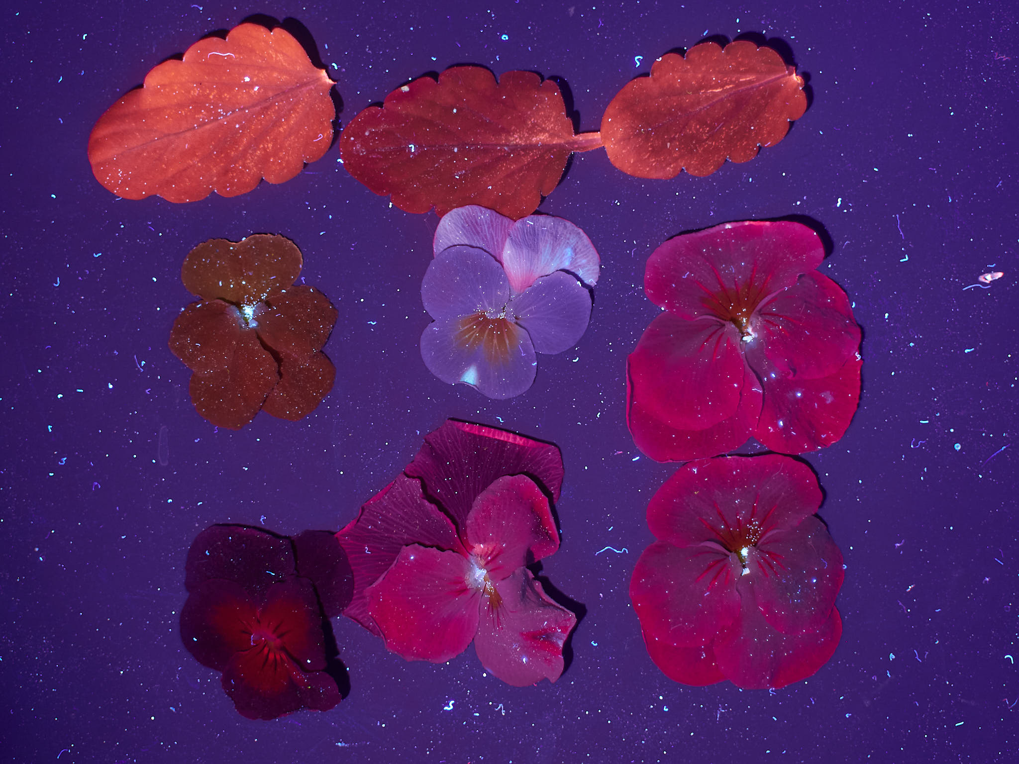
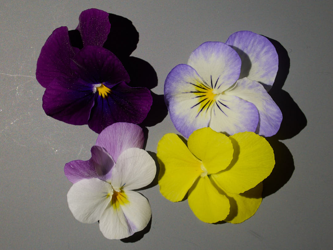
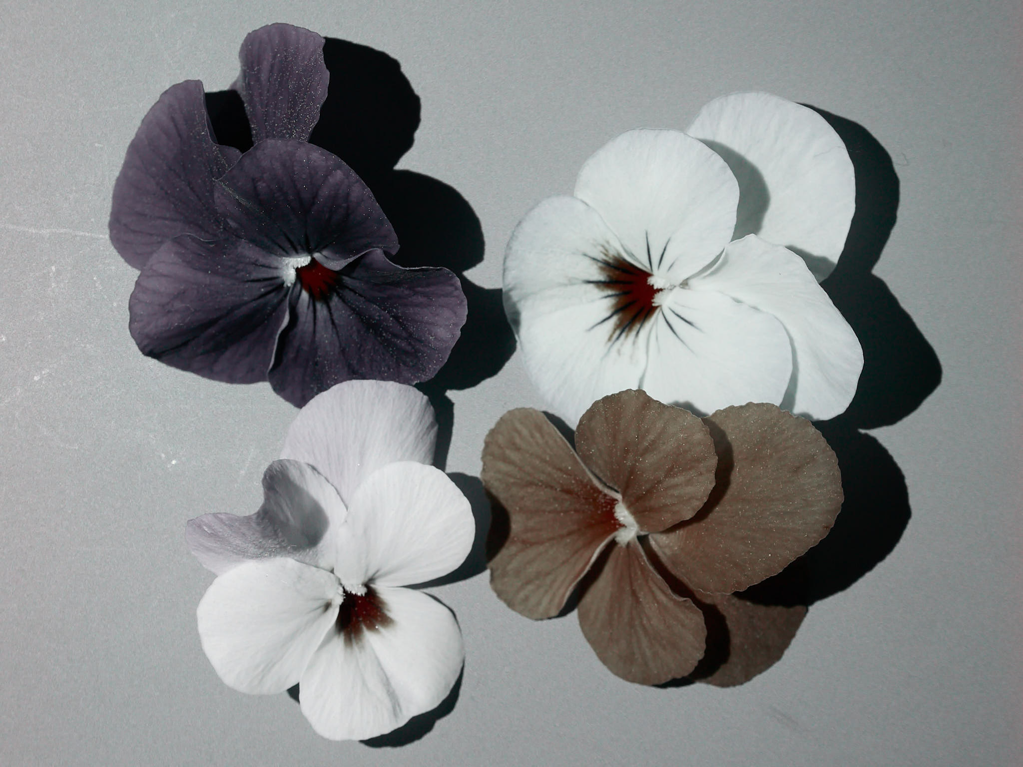
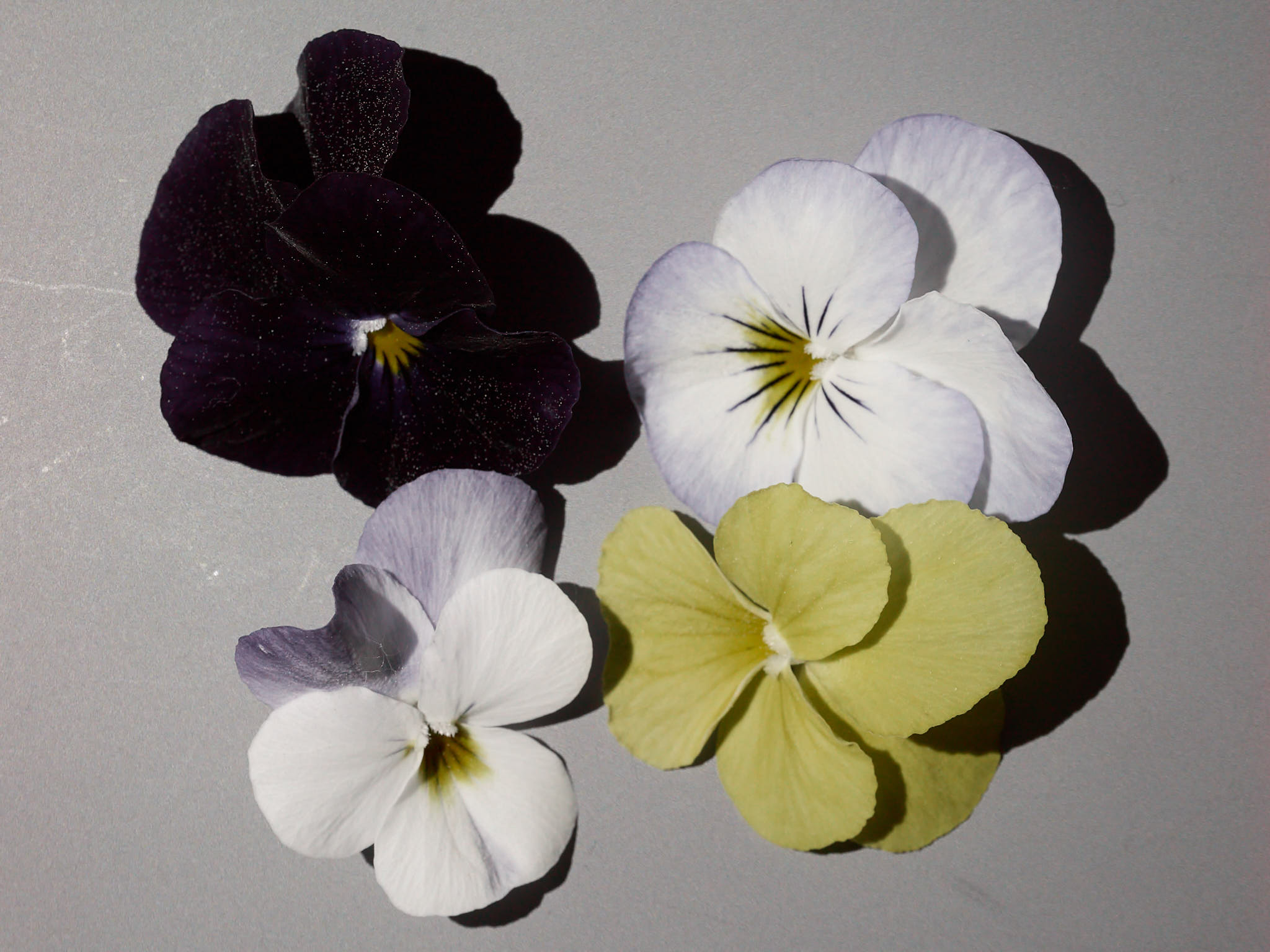
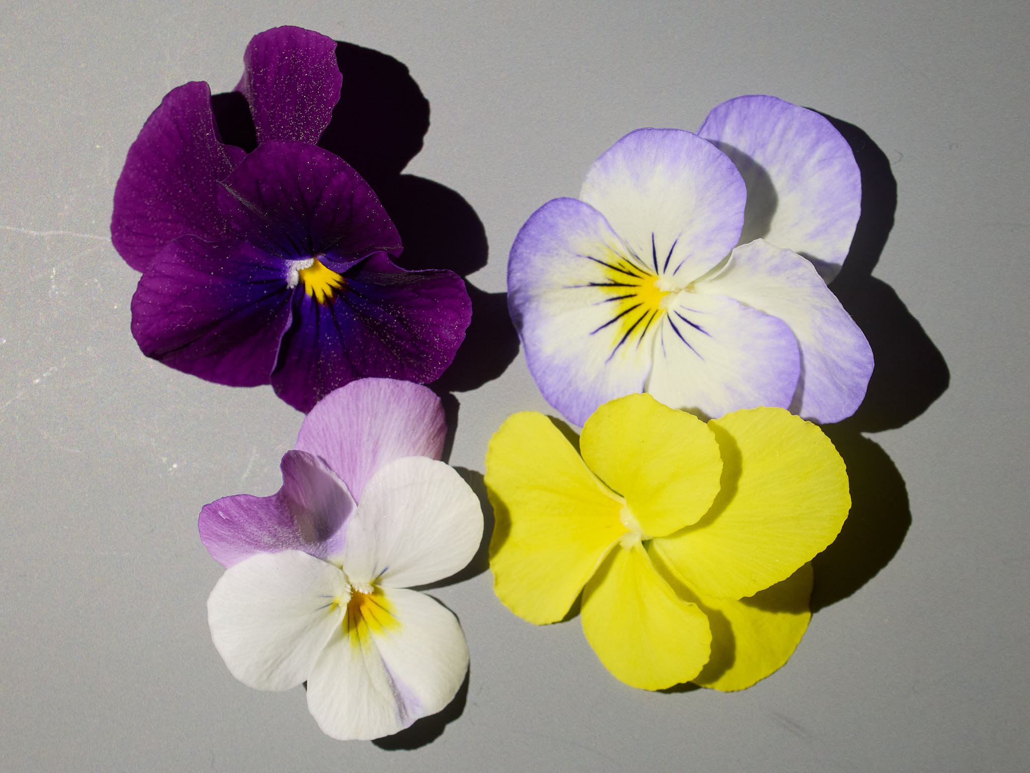
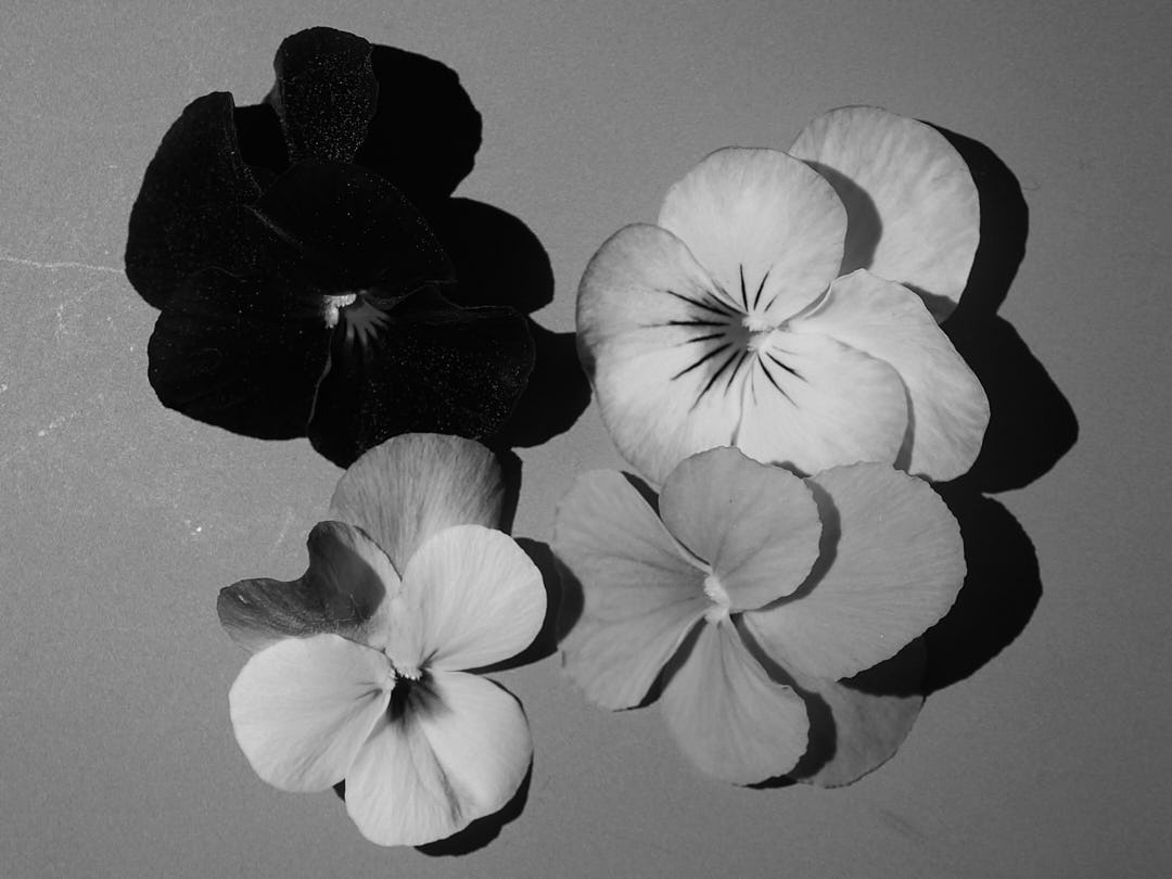
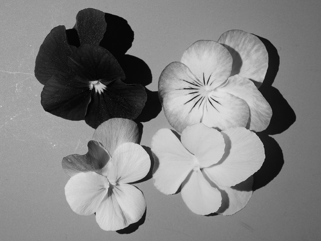
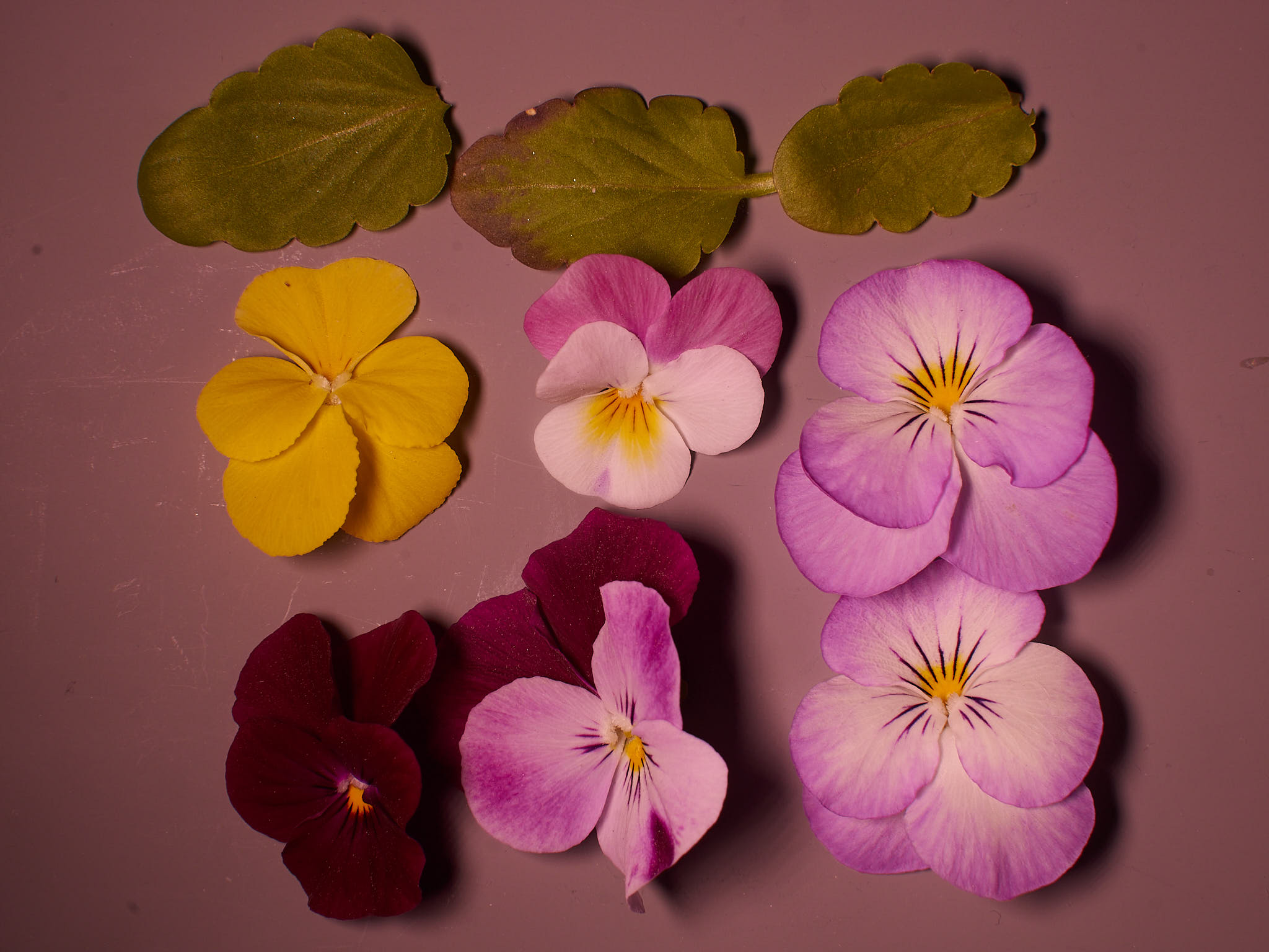
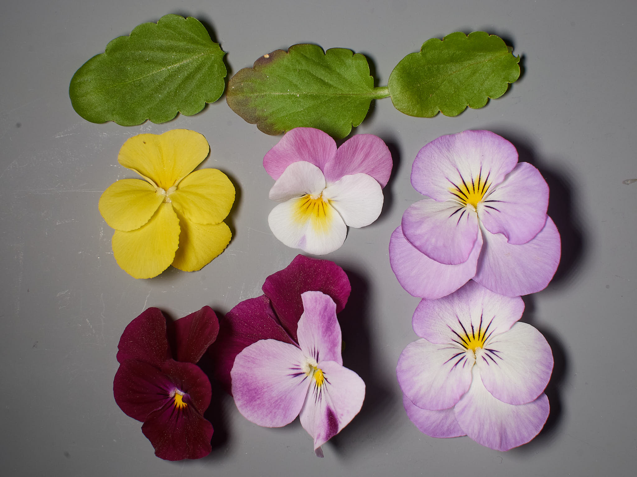
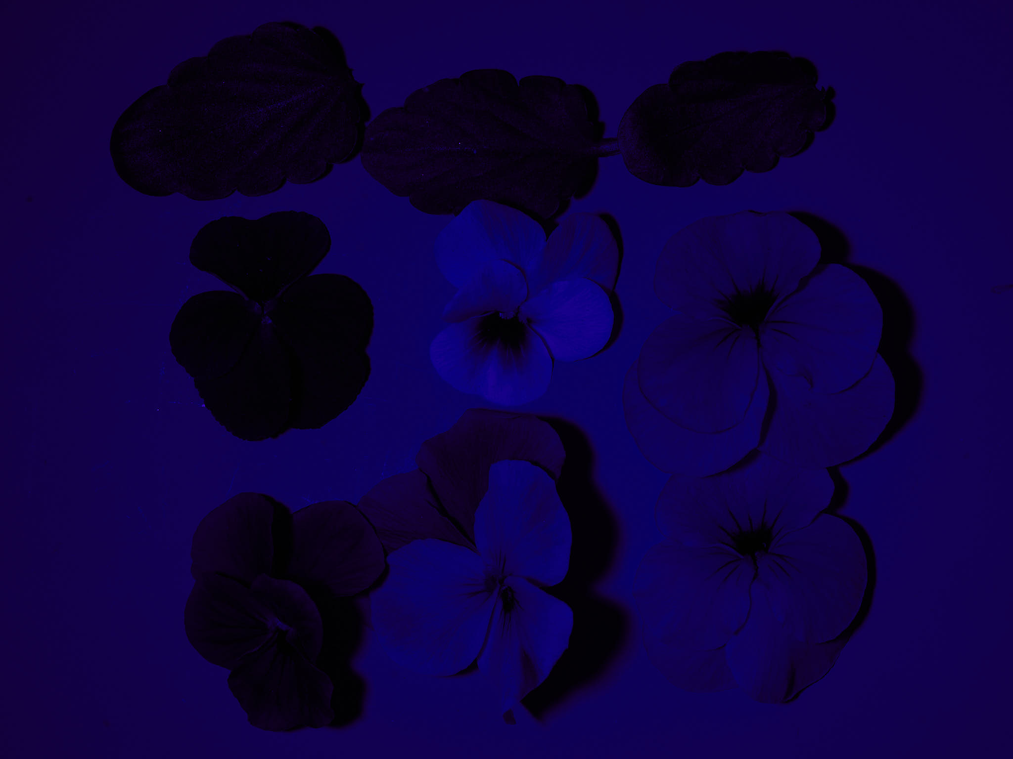
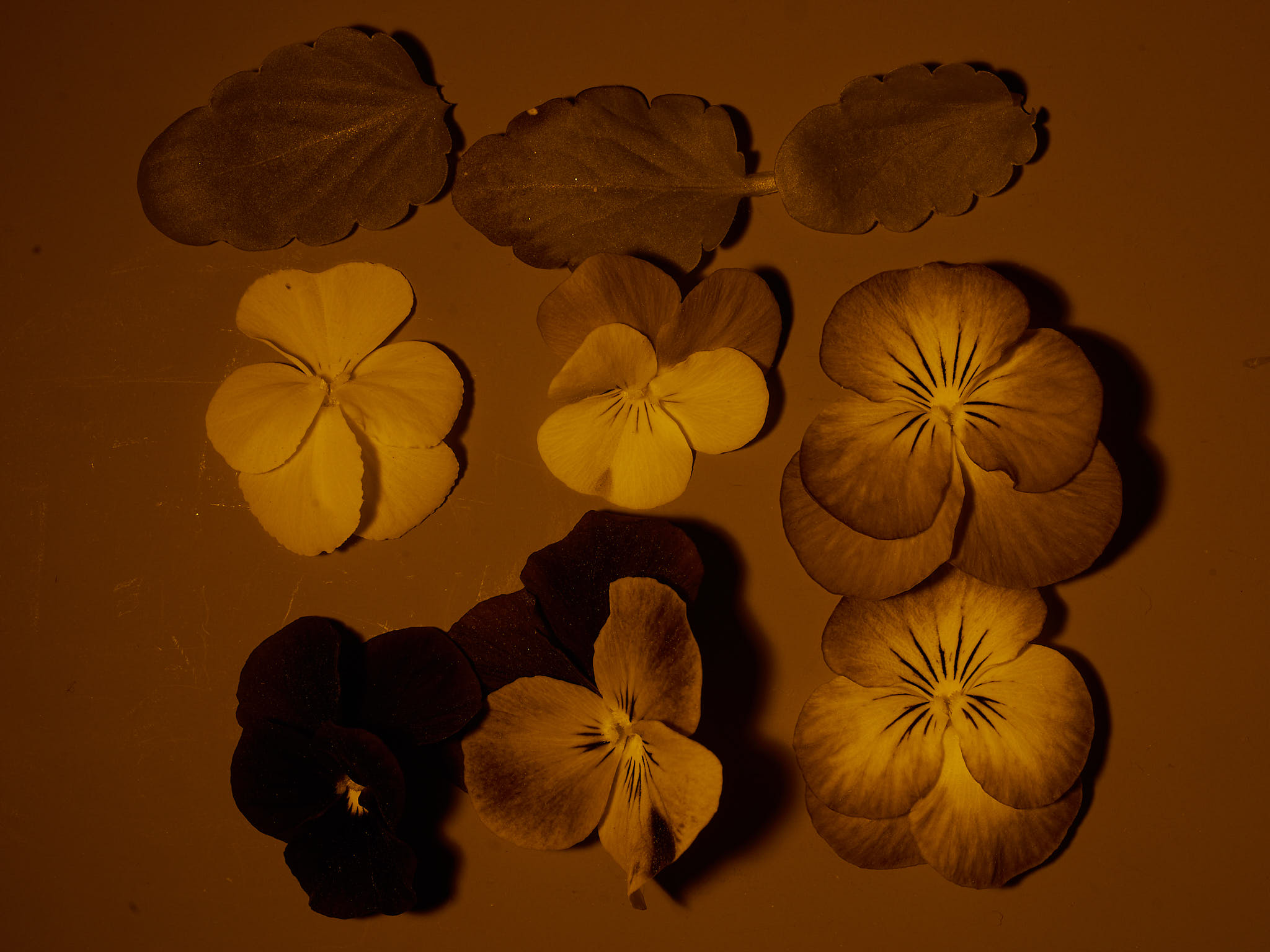
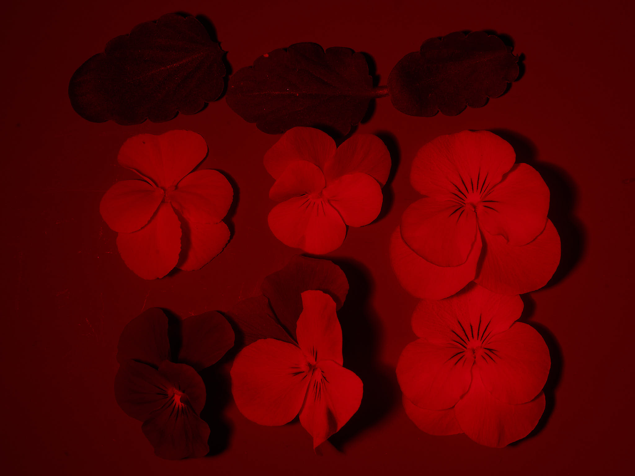
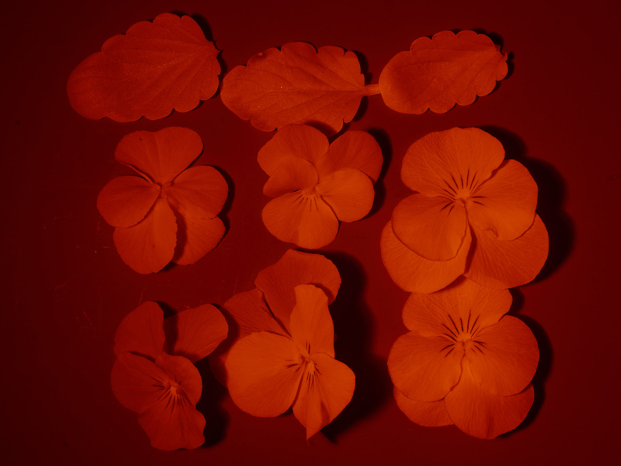
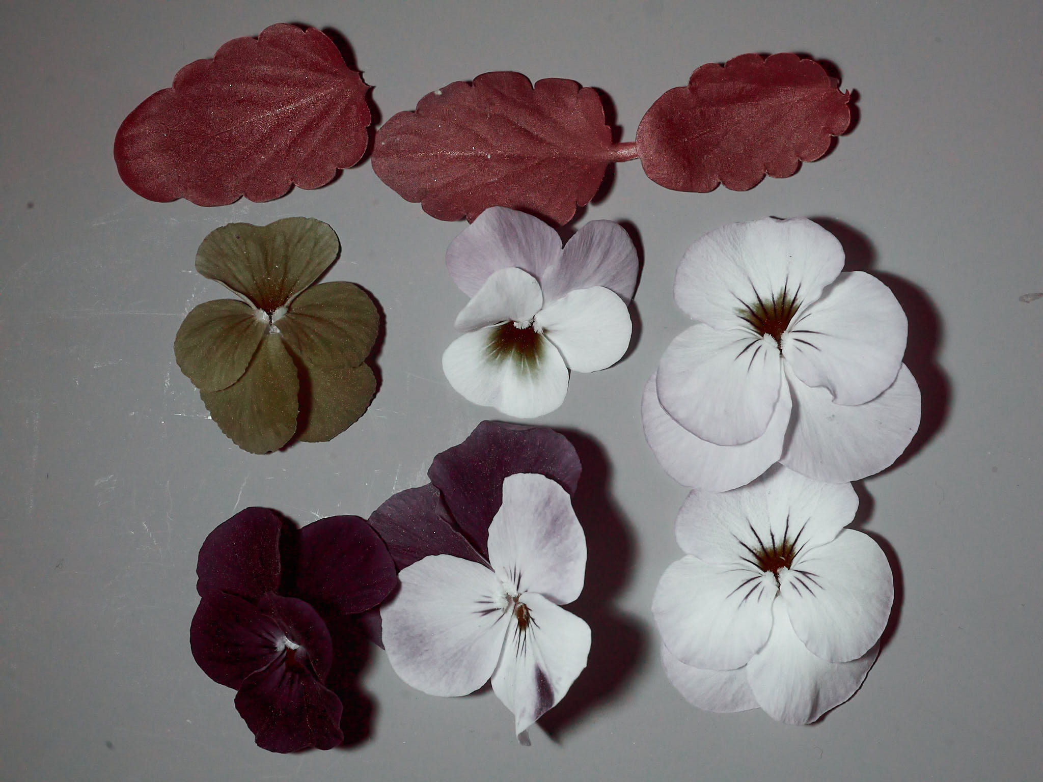
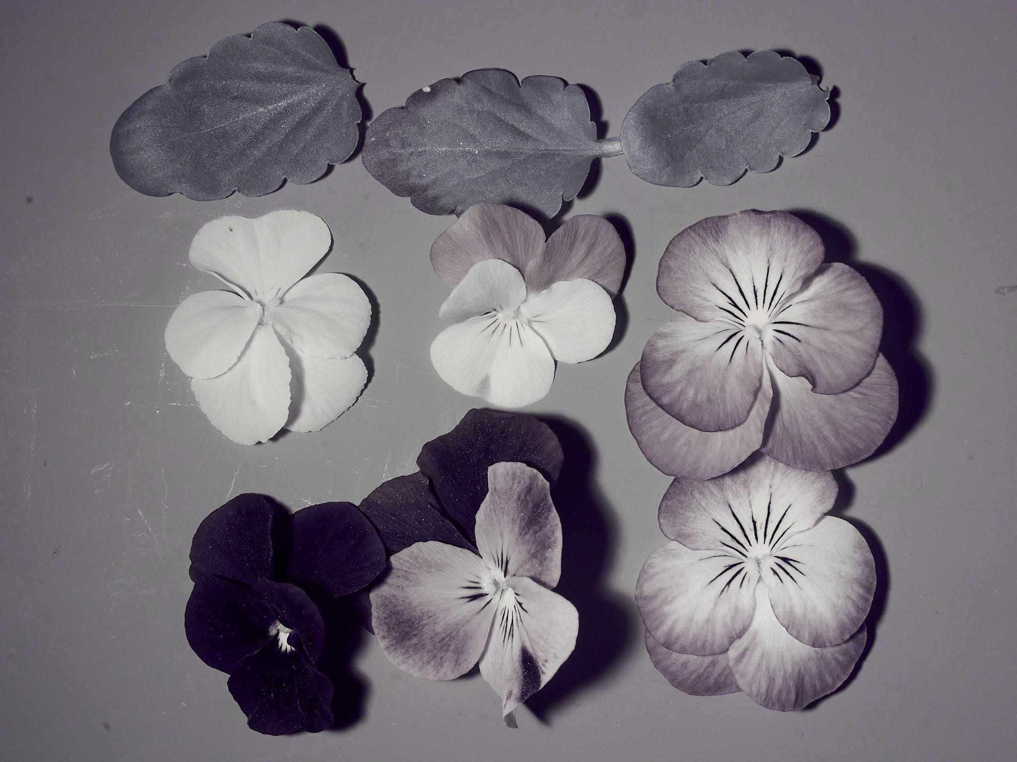
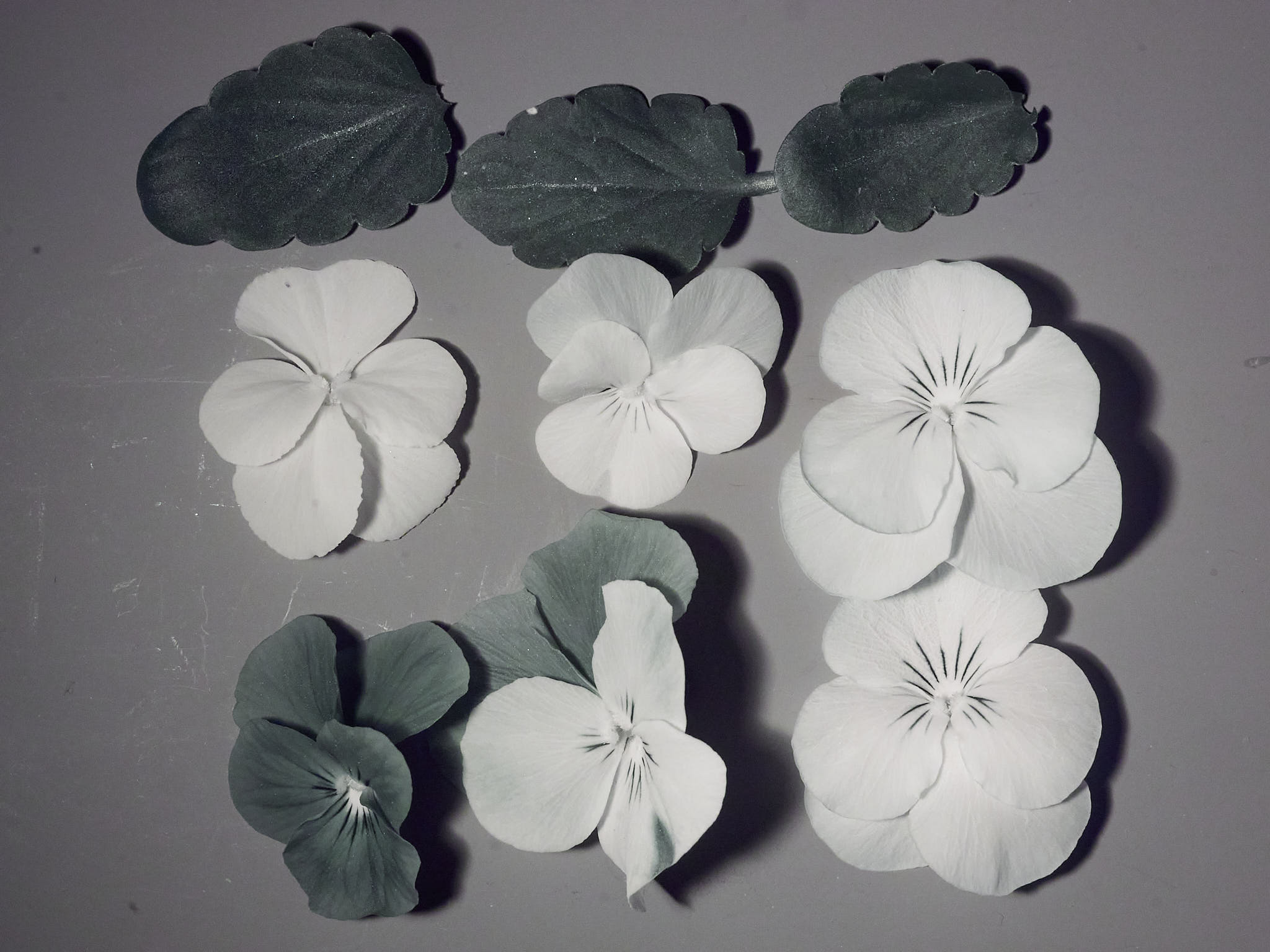
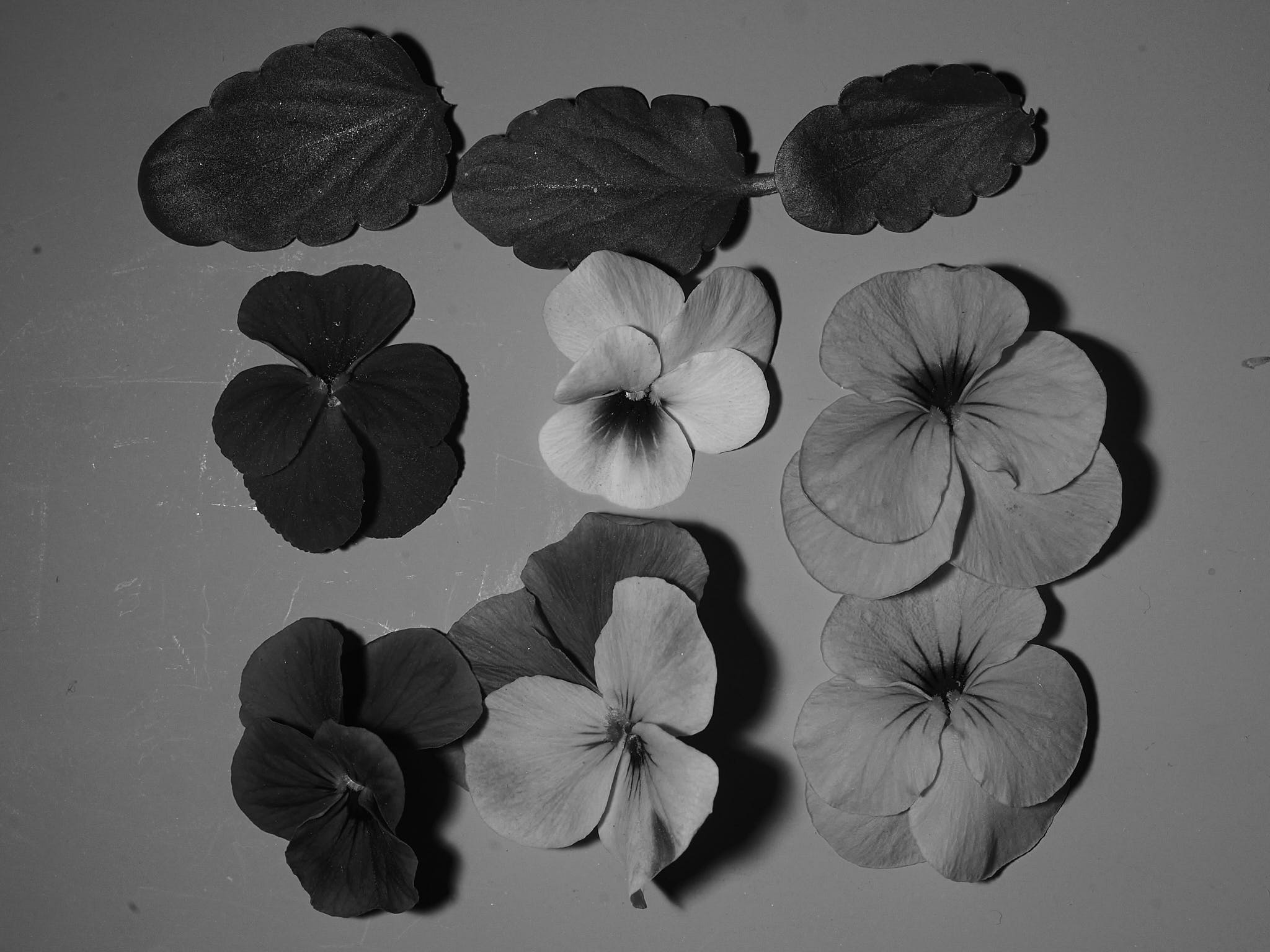
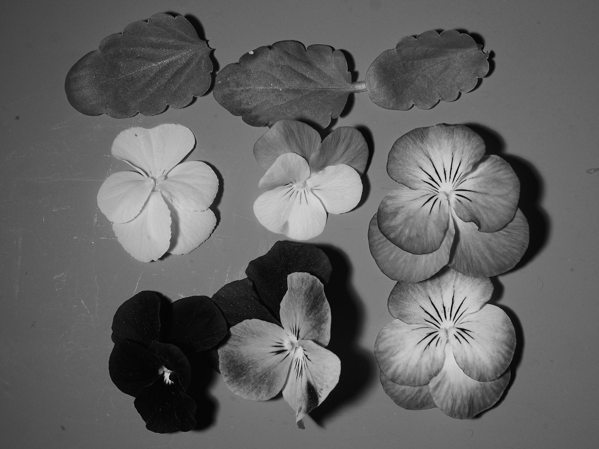
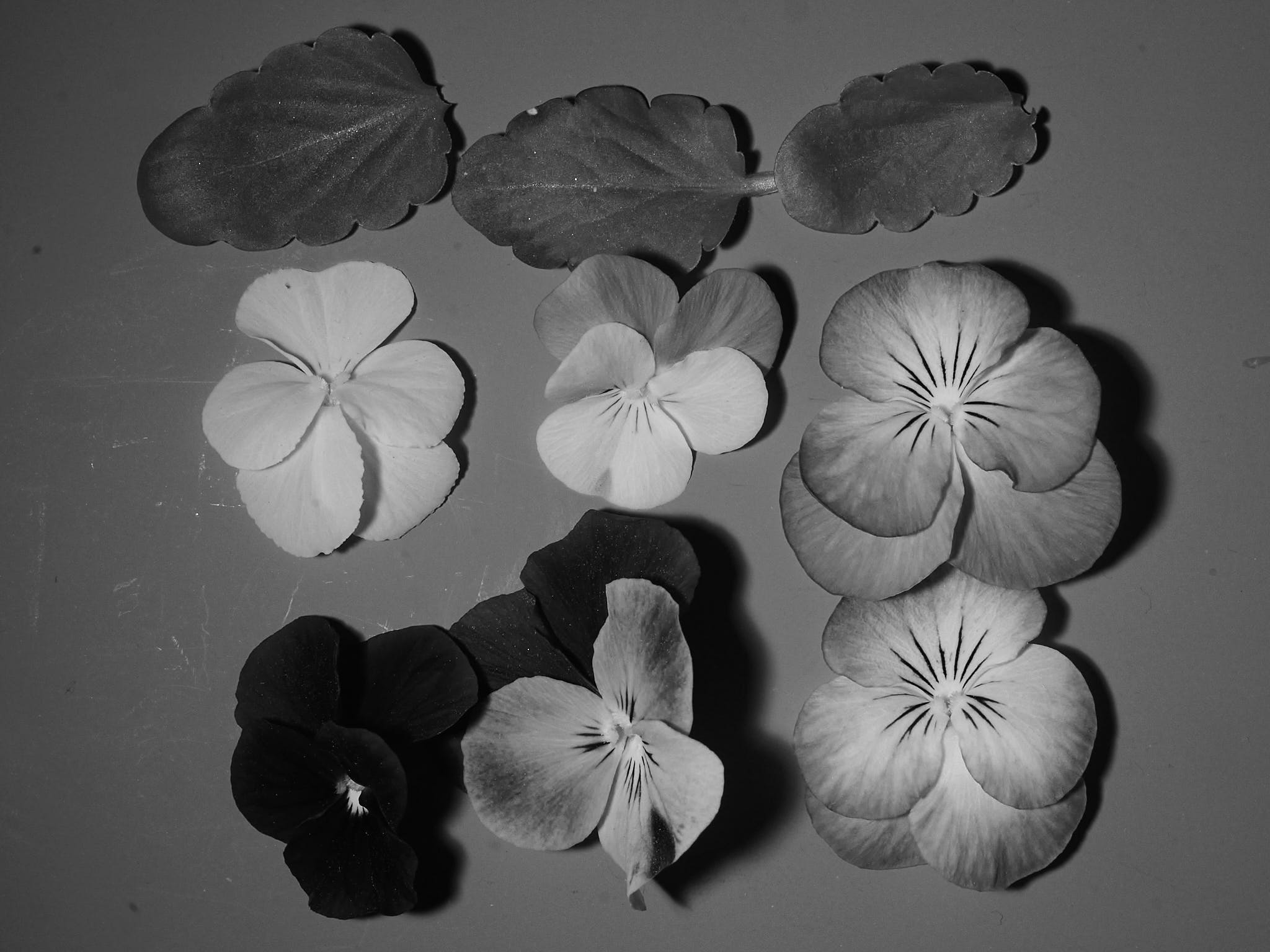
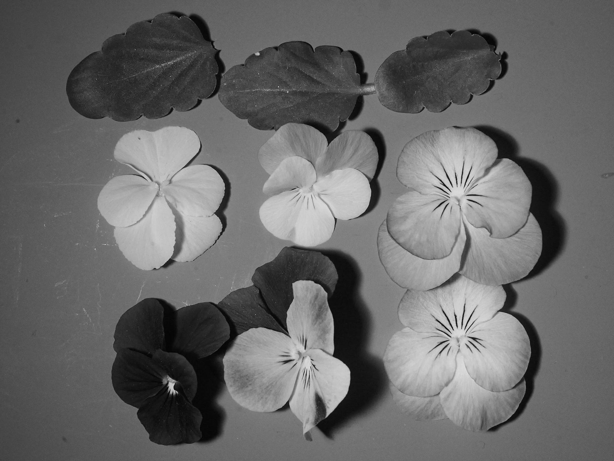
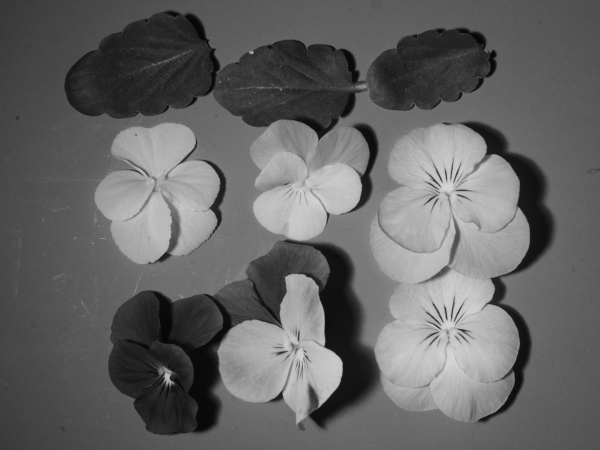
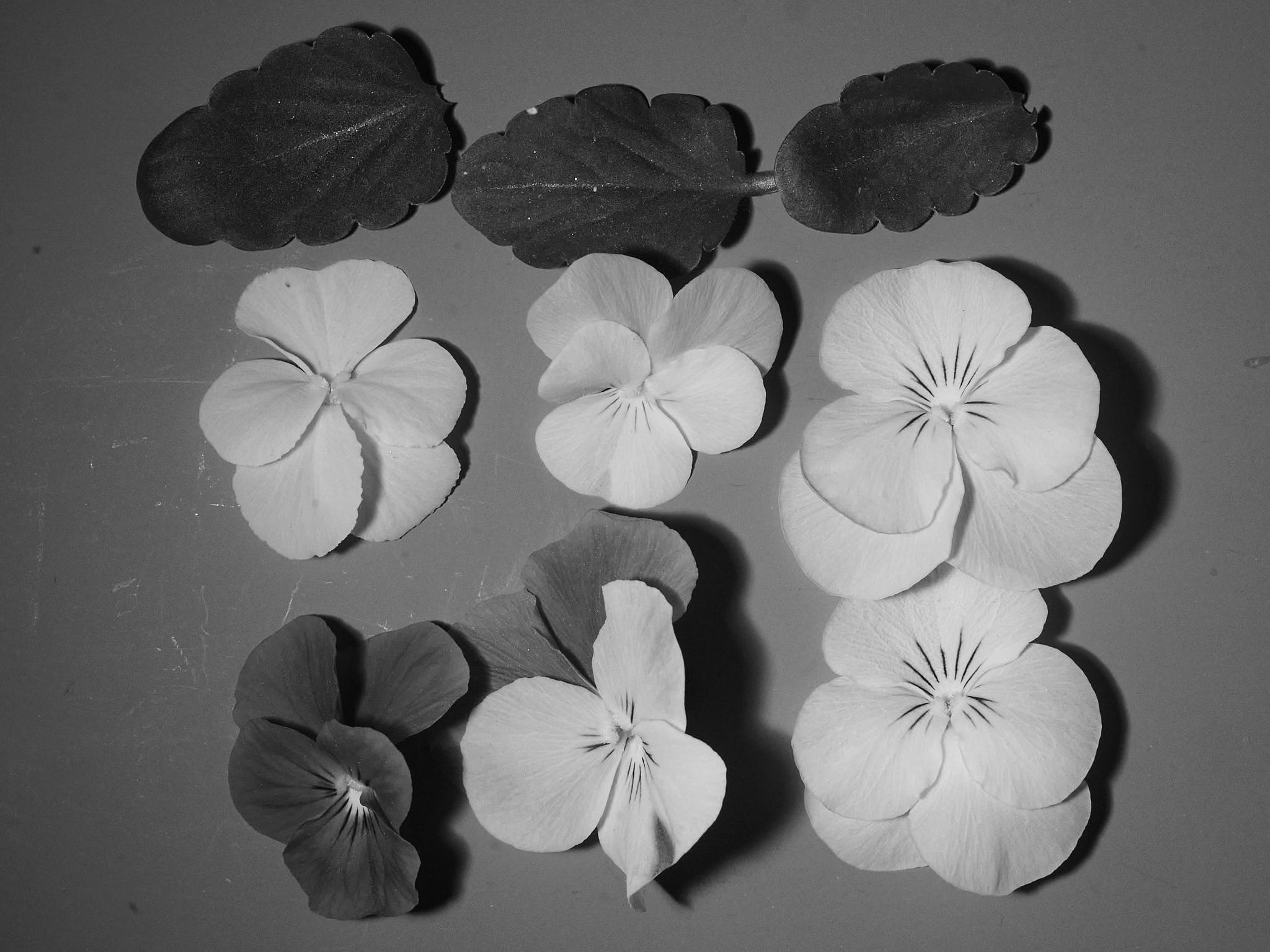
For the first test I picked four pansy flowers from the balcony. For each image I also took images with the LED switched off in the same room as dark control (Figure 4).
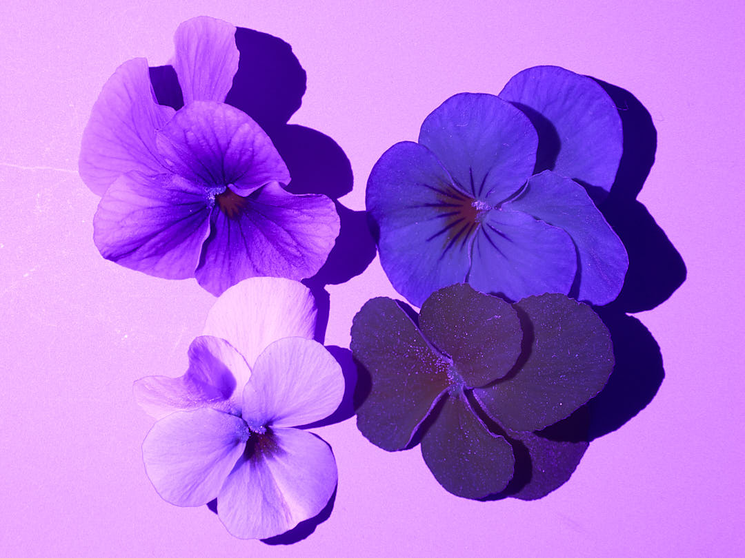
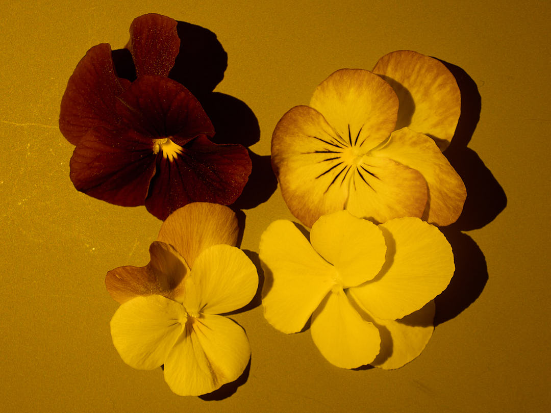
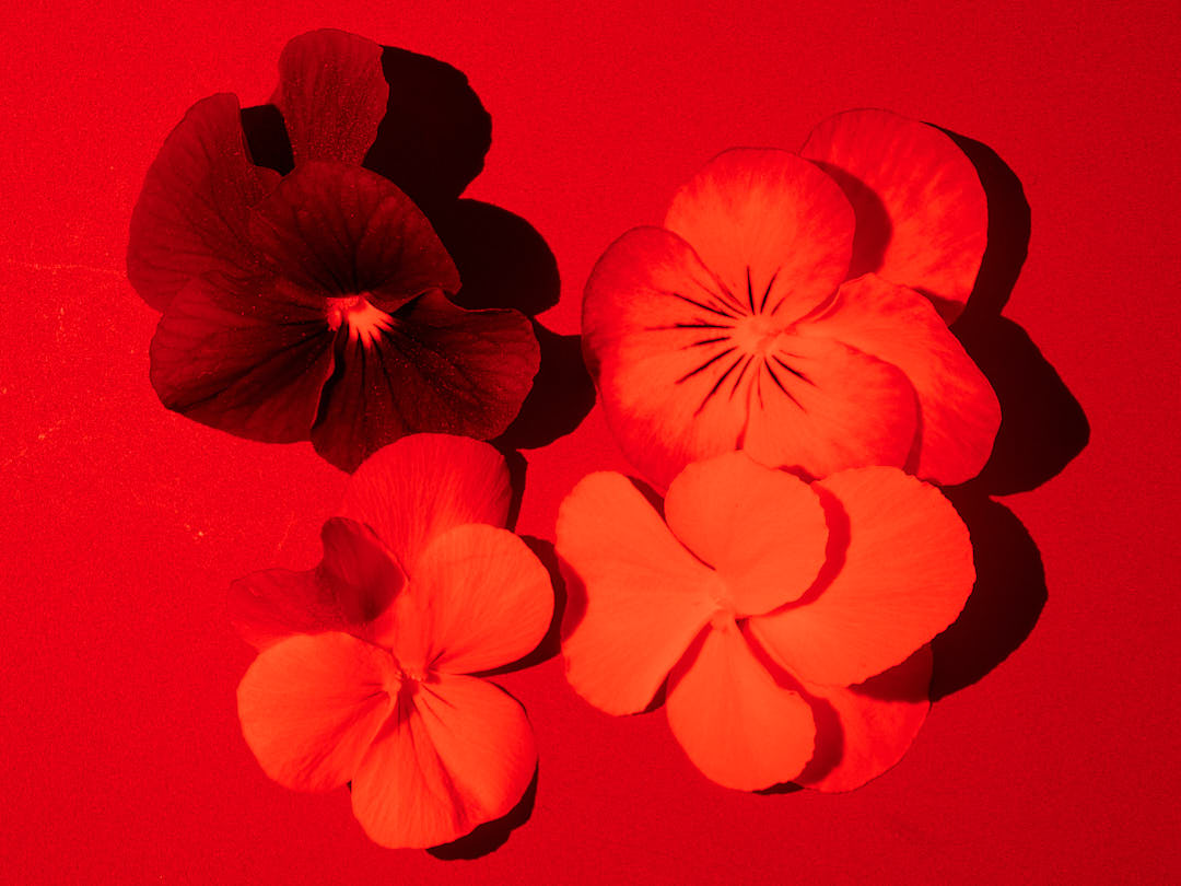
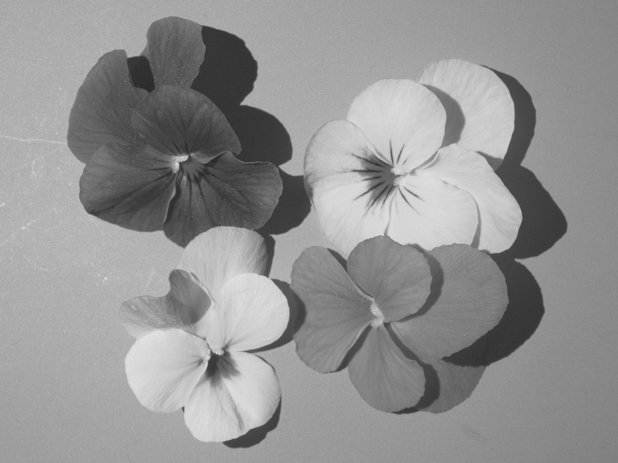
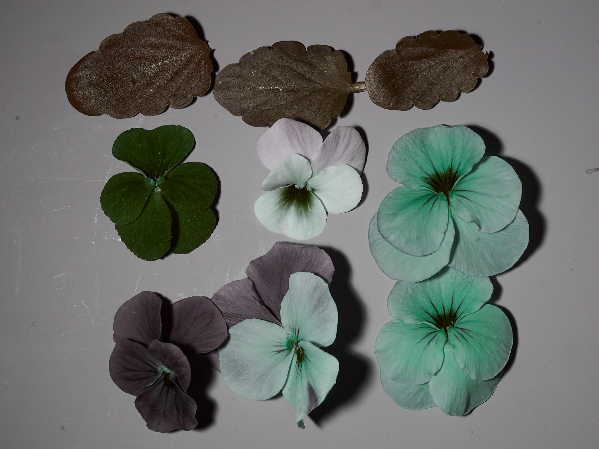
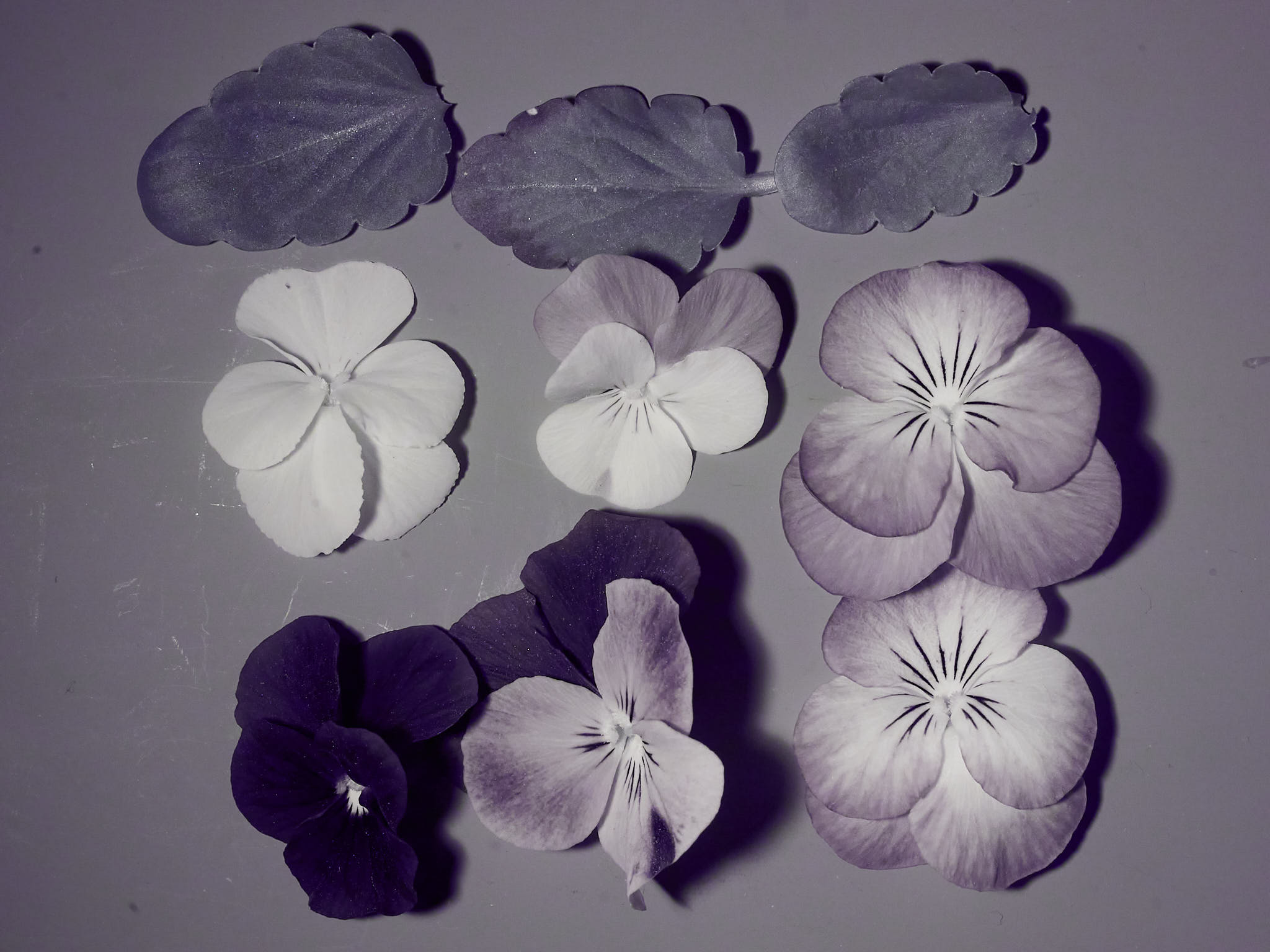
The RGB filters on the camera sensor see to some extent other wavelengths, so white balancing the images based on the grey reference with 18% reflectance used as a background results in false-colour images (Figure 5).
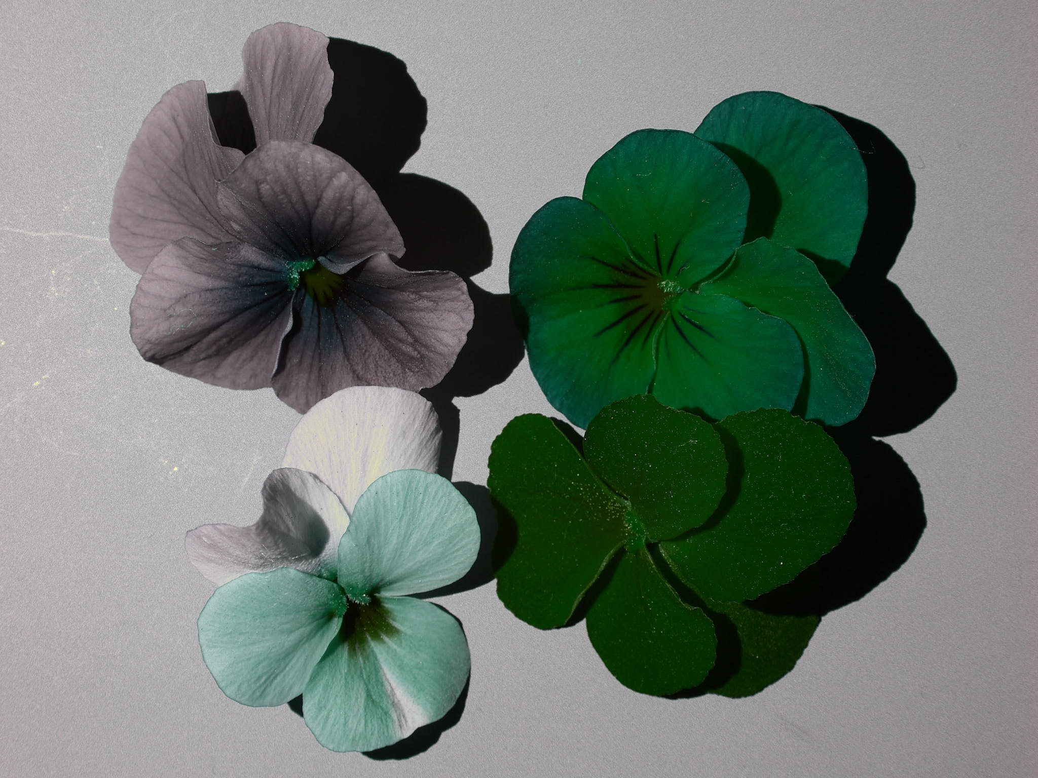
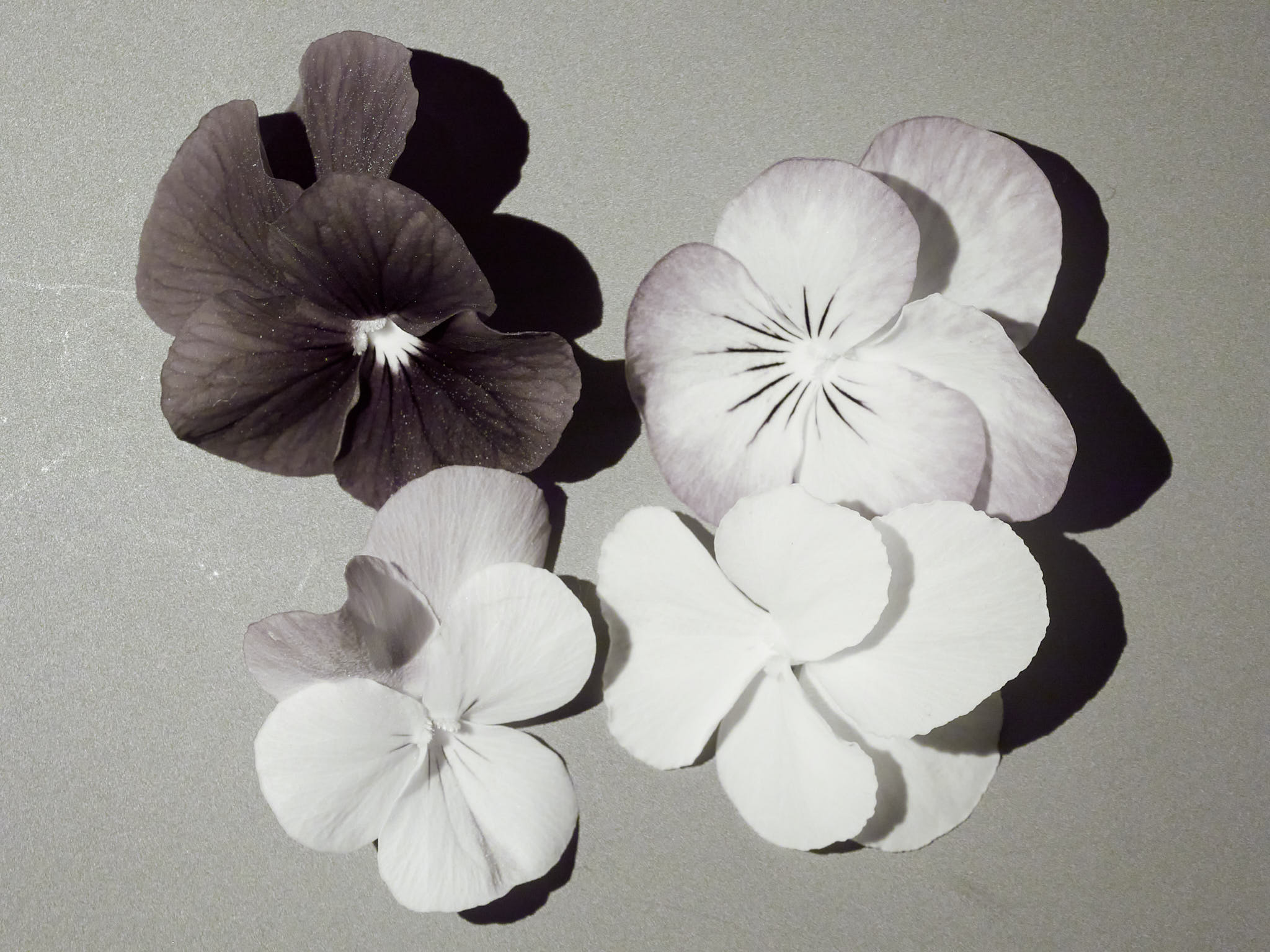
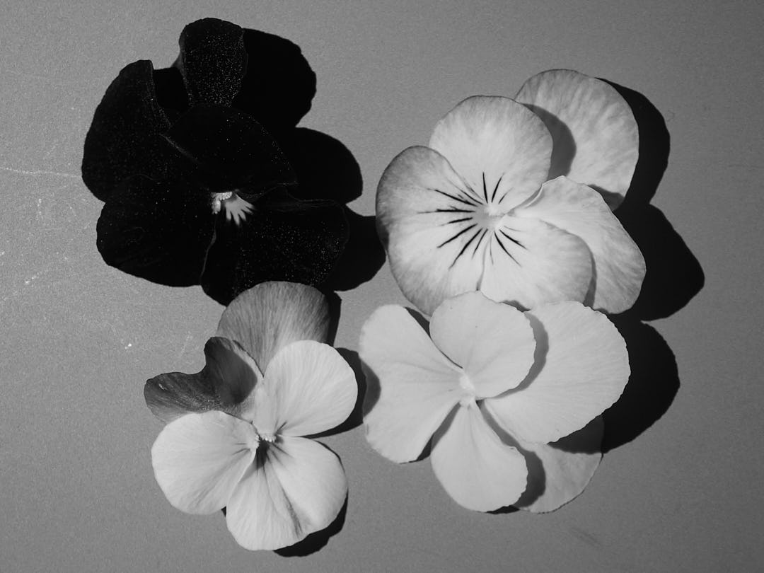
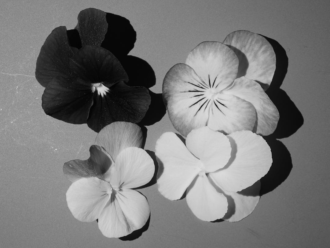
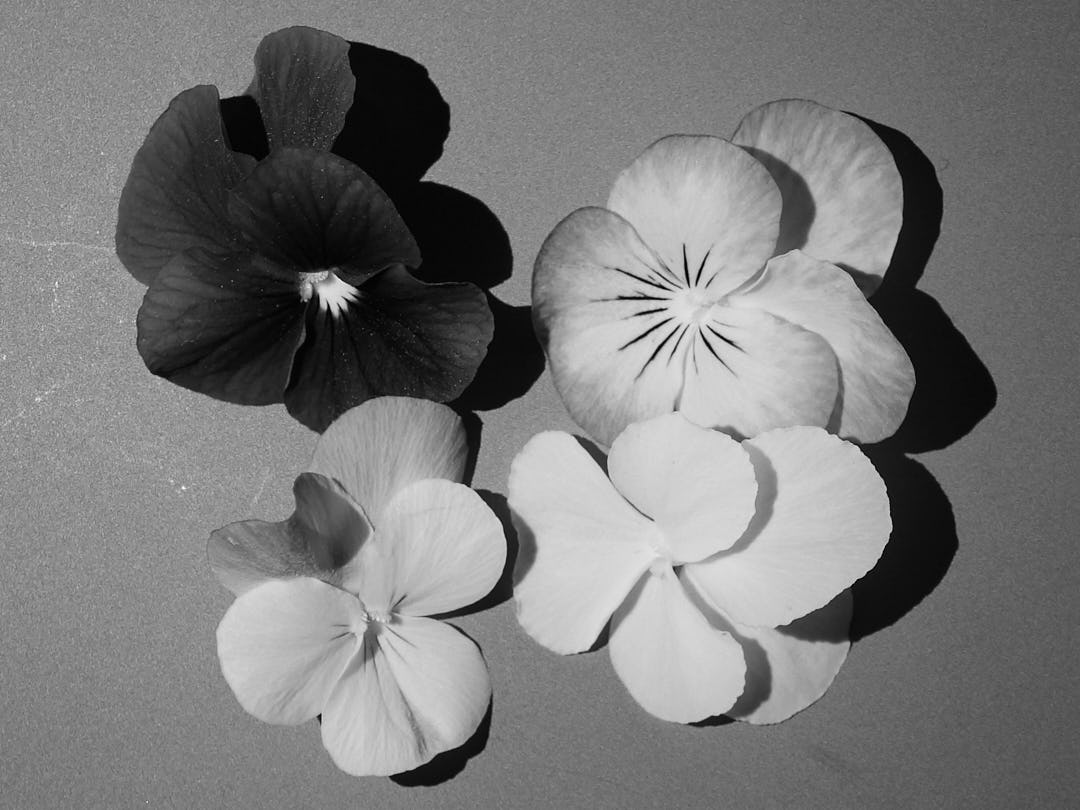
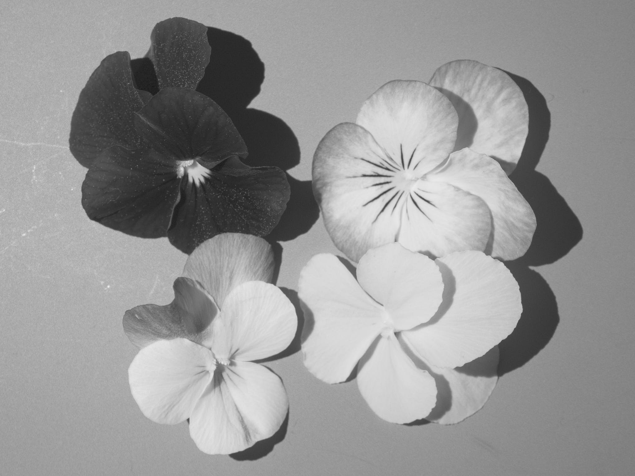
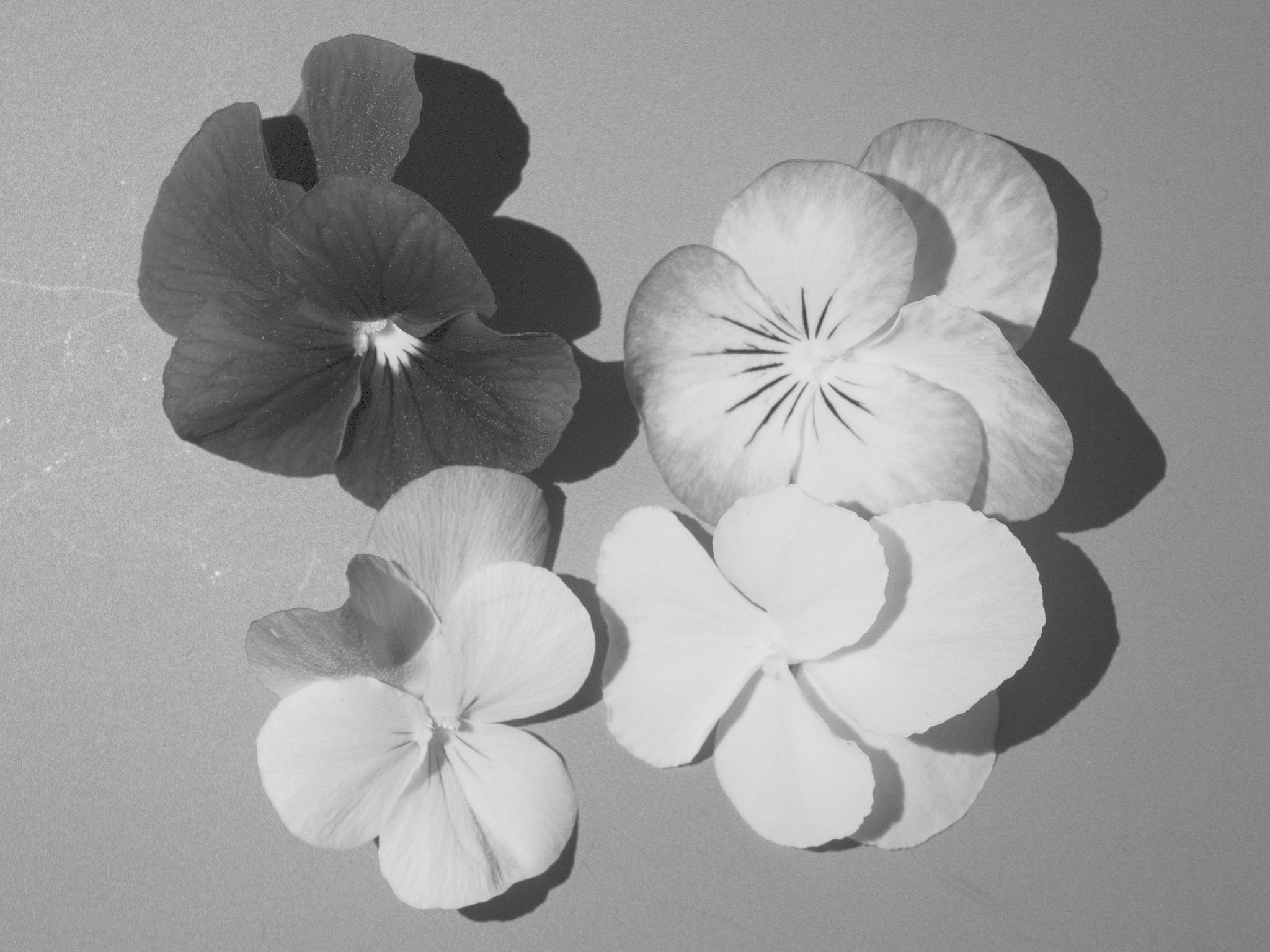
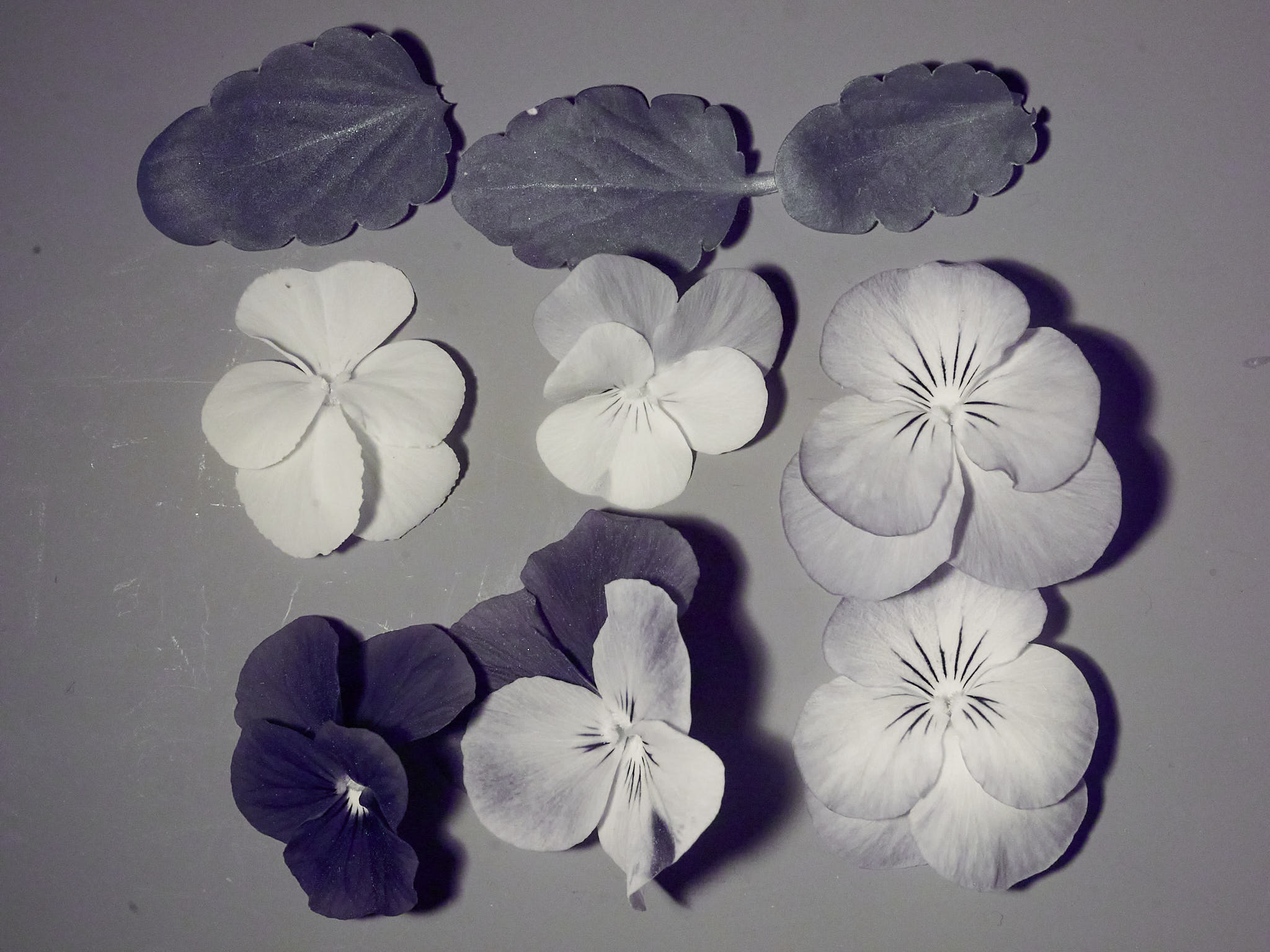
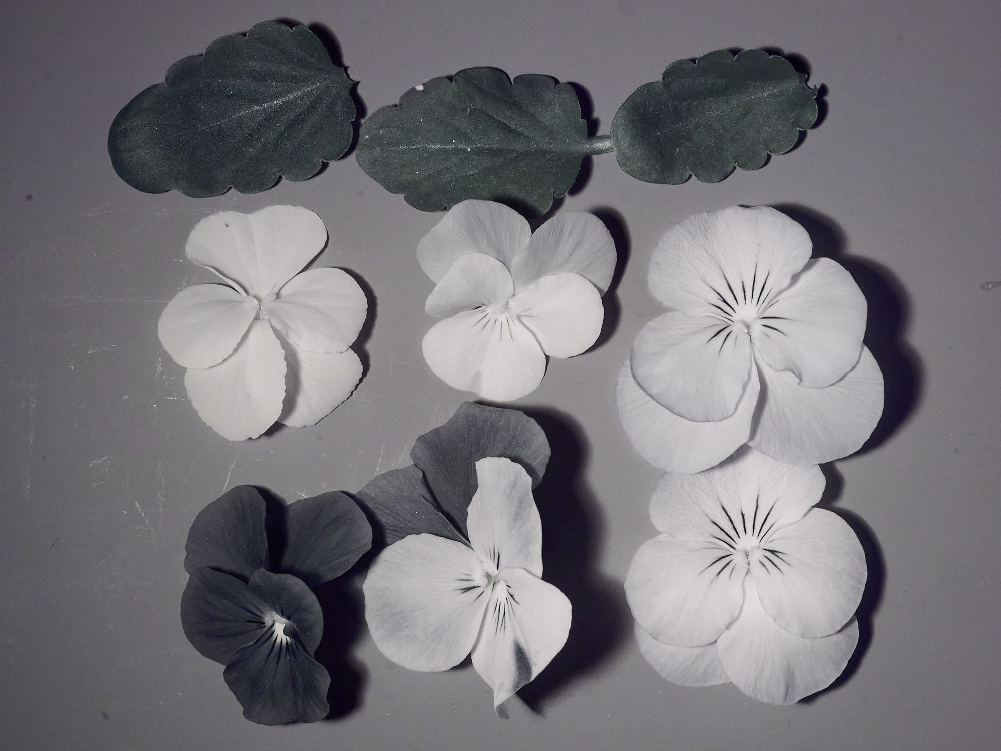
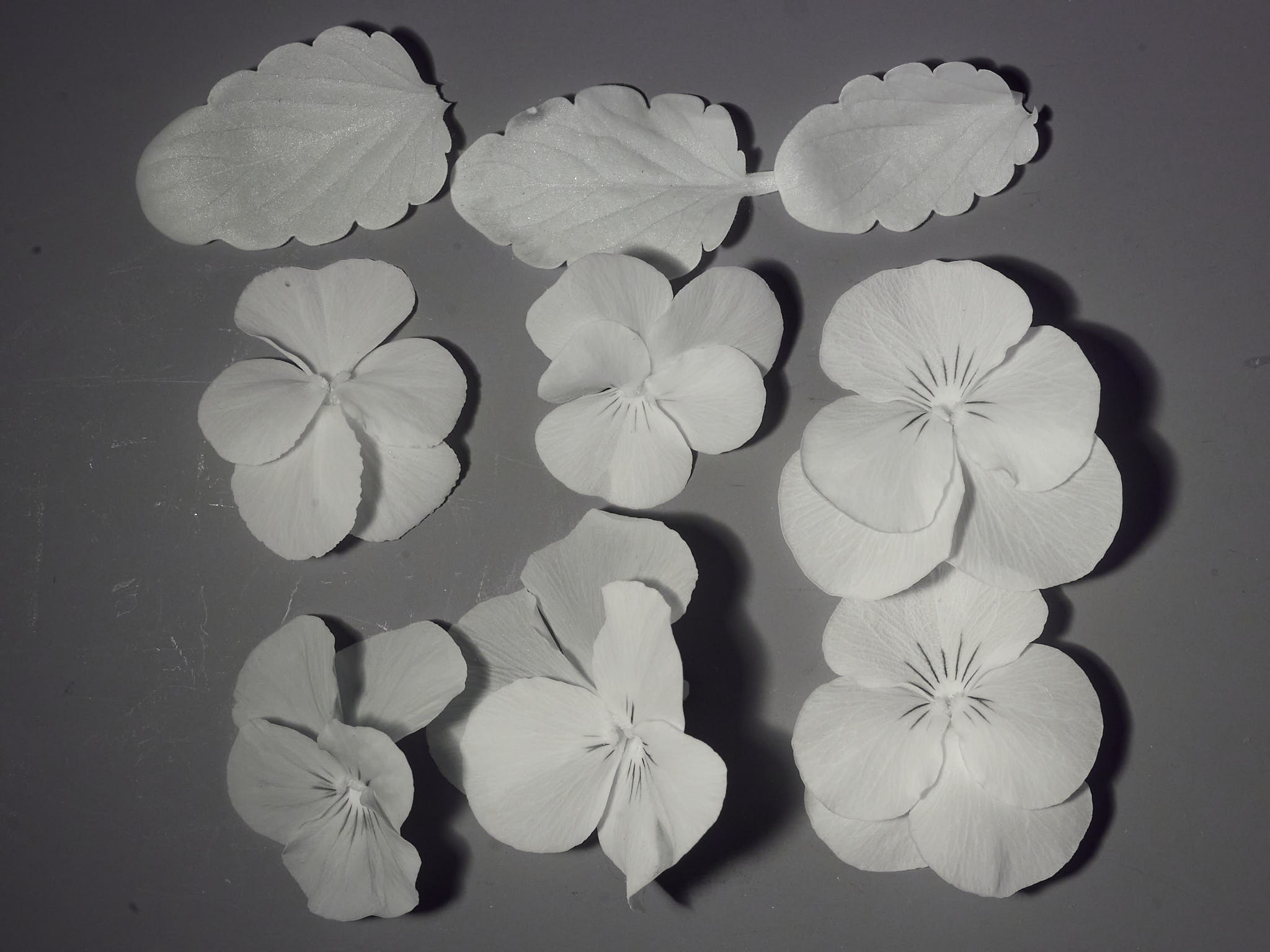
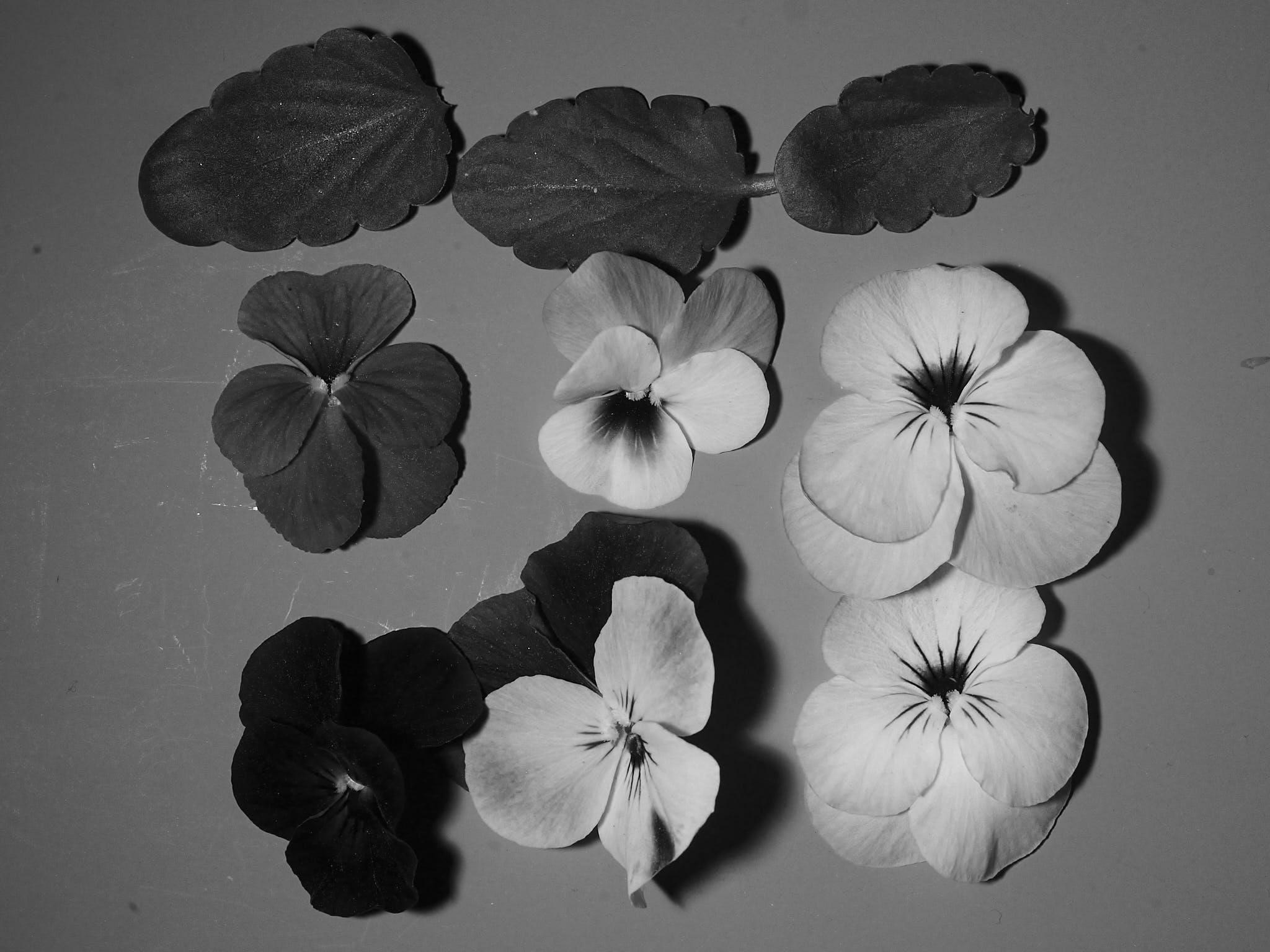
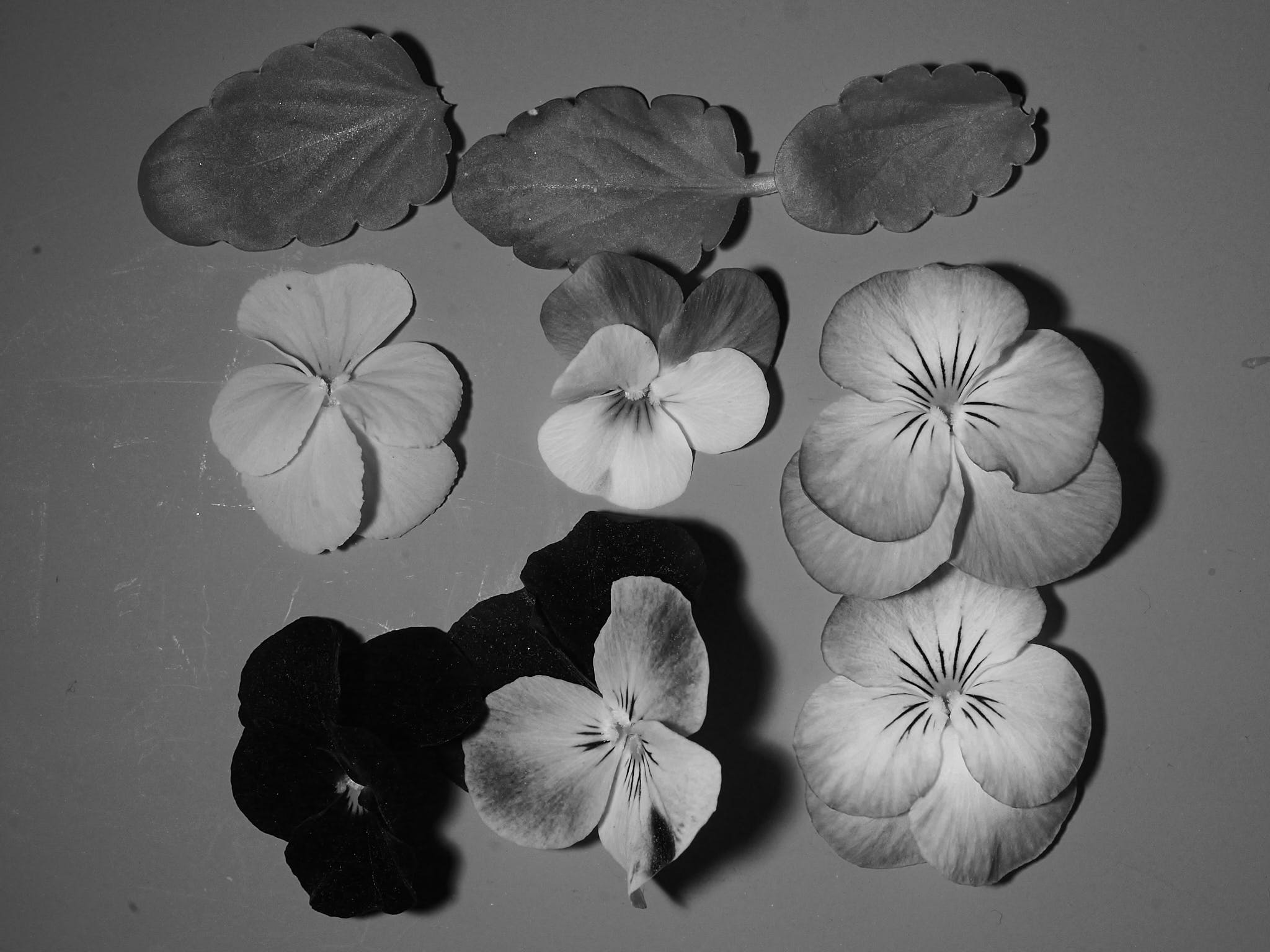
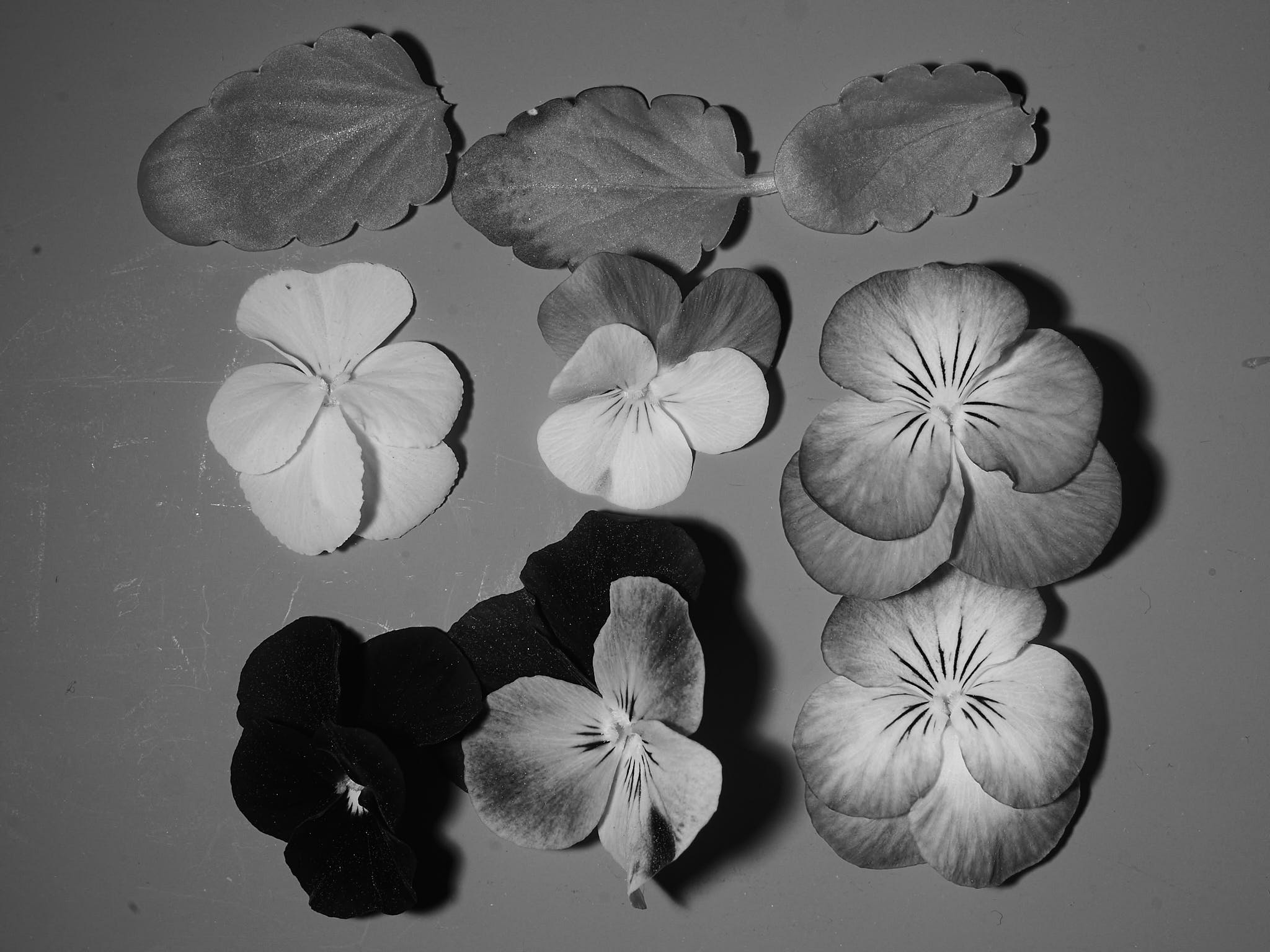
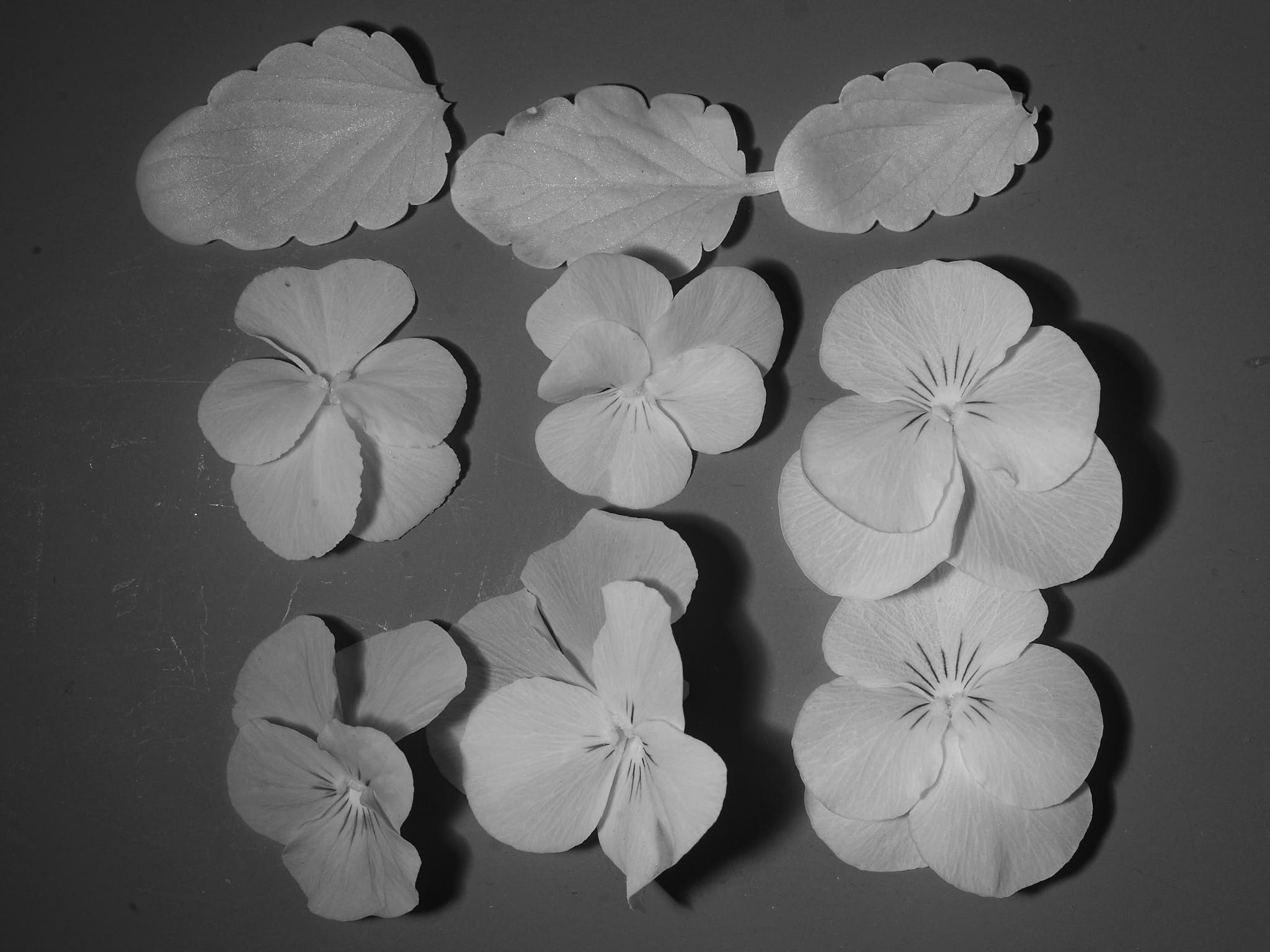
By converting the images to greyscale one can get a estimate of relative reflectance (Figure 6).
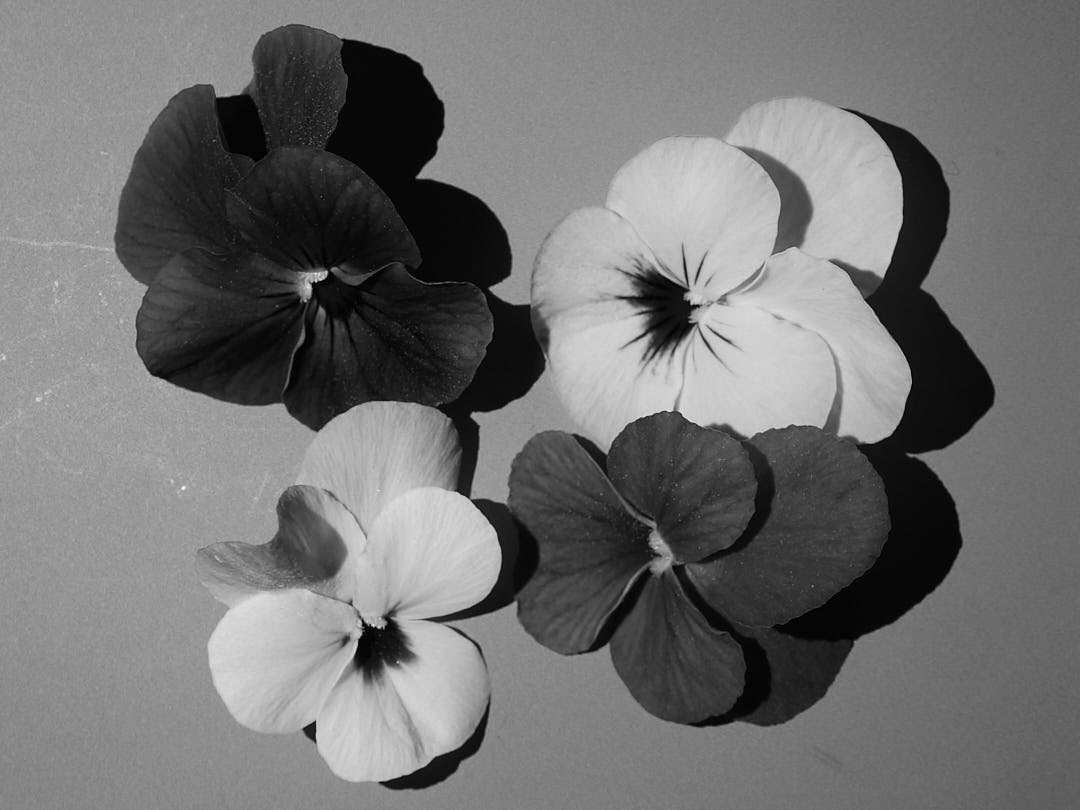
For a comparison we can extract the three channels from the RGB image taken under white light.
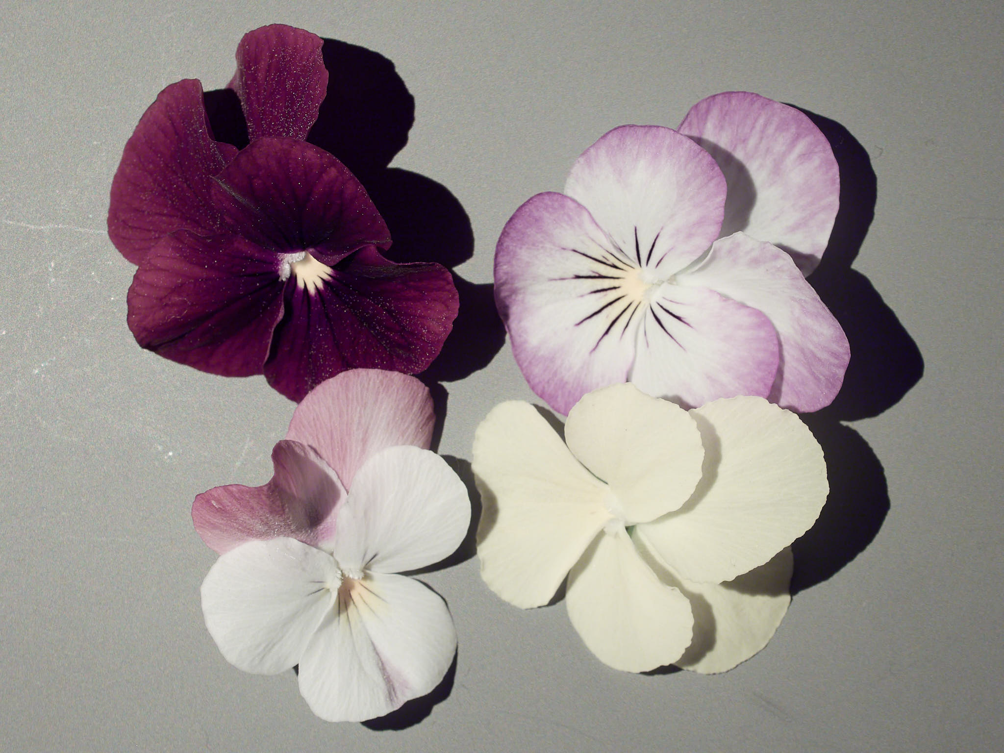
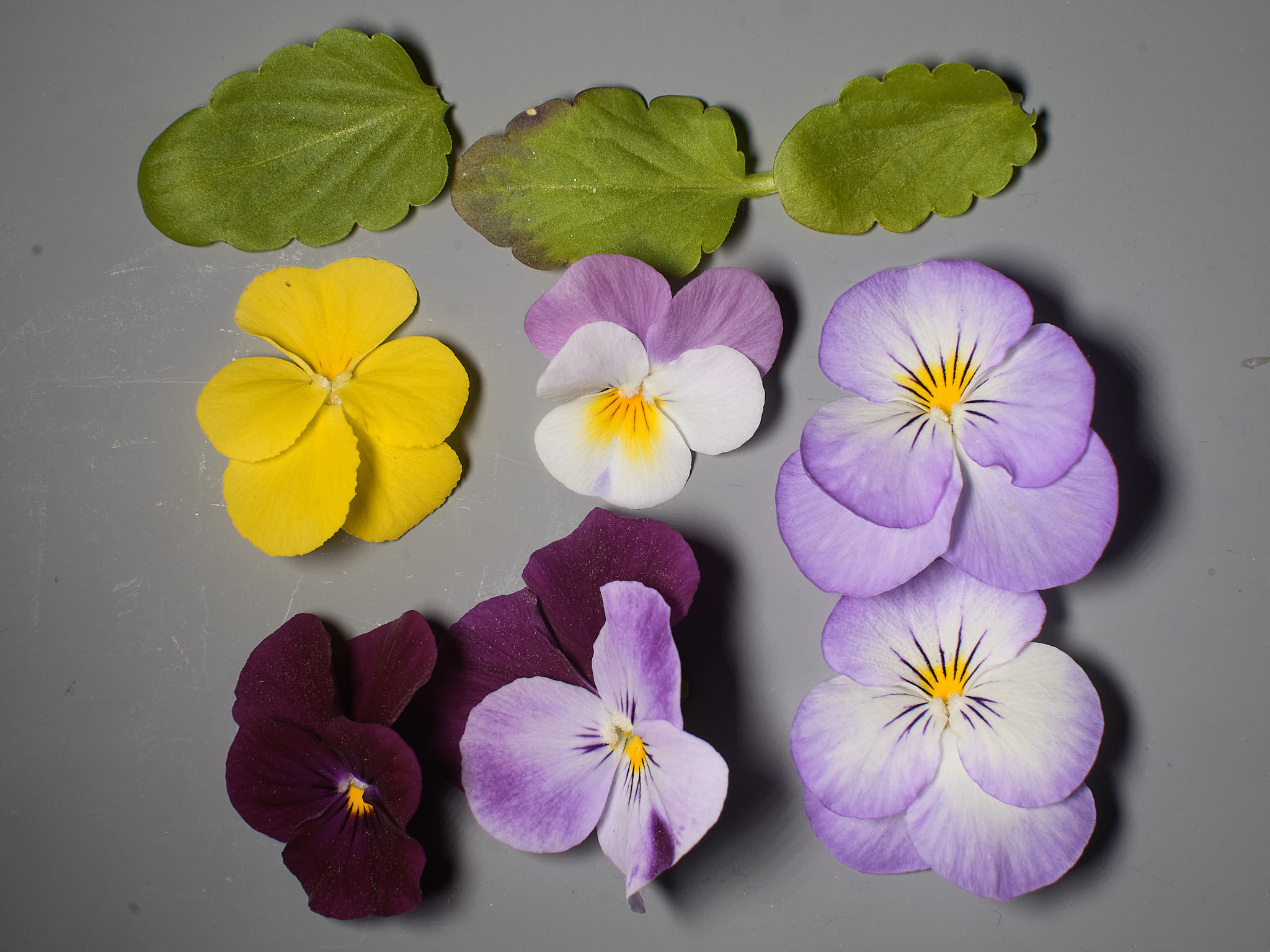
For the images in this chapter I used a different camera, an Olympus E-M1. This older camera has been modified to increase its sensitivity to ultraviolet and infrared radiation. I also used a different objective, a Sigma 30 mm 1:2.8 Art for MFT. This is one of the few modern lenses with accidental extended transmission into the ultraviolet and good performance in the IR. This is no a macro lens and I used it very near its closest focusing distance. The images were taken on a different so the flowers are not the same as above but they do come from the same plants. The increased sensitivity to red light affects the colour rendering even when using a white LED source with a CRI \(\approx 95\), and a truer rendering can be achieved only with a custom colour profile (Figure 8). After applying the ICC profile the colours match well those shown above for the unmodified OM-1 camera.
I have used LEDs from my collection to characterize the spectral response of the RGB channels of this same camera. The measurements are described in the page and help explain the false colours in the images.
The E-M1 has a 16 Mpix sensor, front side illuminated. The photographs were saved as ORF raw files and edited and converted to lower resolution JPEG compressed files for display in this page.
A custom assembled LED array with twelve channels with independent wiring. Ten LED chips (1 W each) connected in series and arranged in a line conform a channel. Total nominal power is 120 W, with 10 W per channel. Nominal maximum current per channel is 350 mA and voltage up to 37 V. The array was supplied by Shenzhen Weili Optical with “family type” G-100PW140AG-M but with my choice of wavelengths.
autoplot(normalise(led_arrays.mspct$Weili_120W.array.12ch.custom.A),
         range = c(350, 850),
         geom = "spct",
         w.band = VIS_bands()) +
  theme_bw() + theme(legend.position = "none")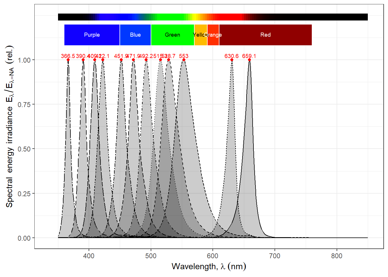
This array is identical to type A but differs on the selections of wavelengths in the channels, being more spaced in short-wavelength end of the spectrum and reaching farther in the long-wavelengths end.
autoplot(normalise(led_arrays.mspct$Weili_120W.array.12ch.custom.B),
         range = c(350, 850),
         geom = "spct",
         w.band = VIS_bands()) +
  theme_bw() + theme(legend.position = "none")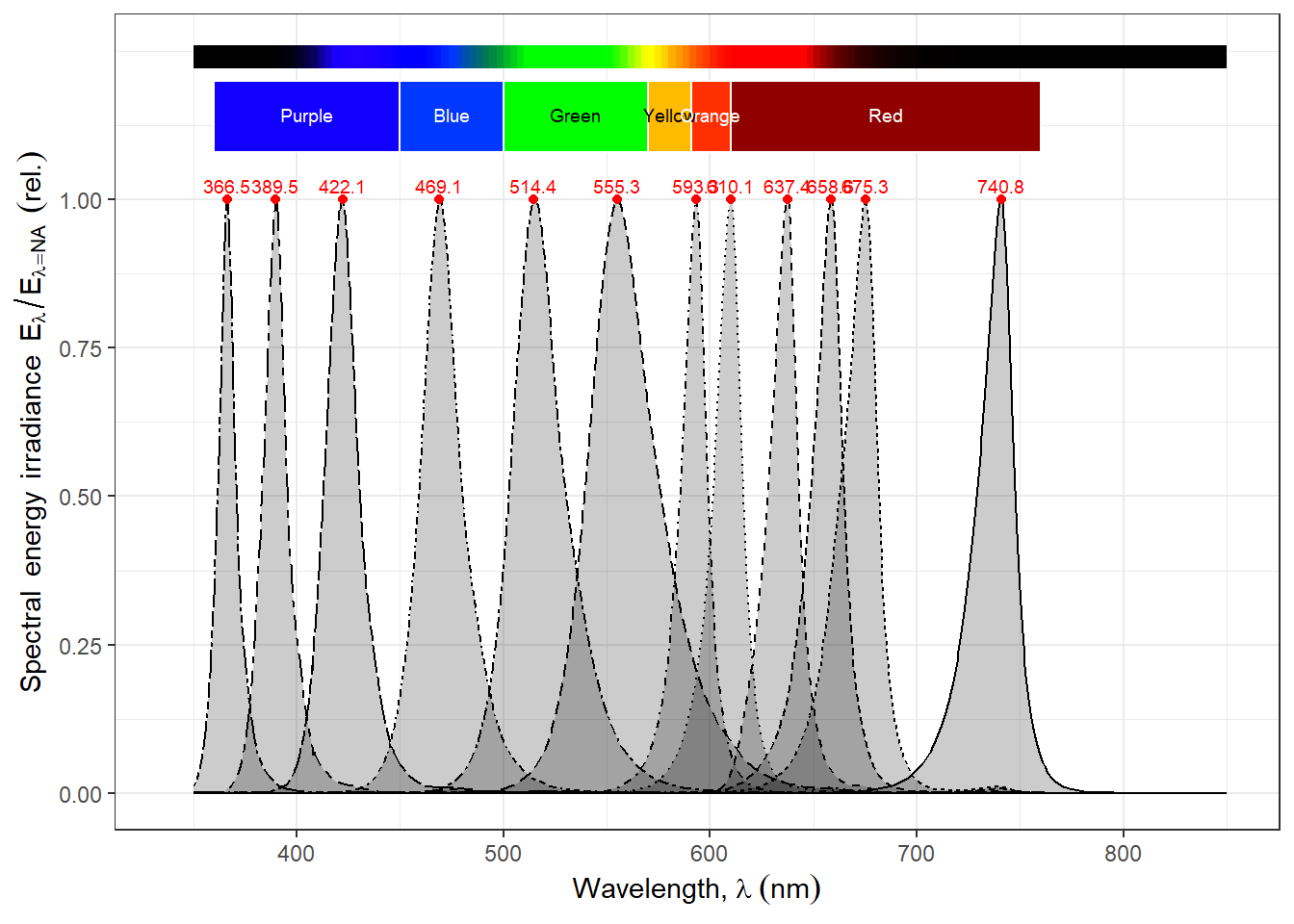
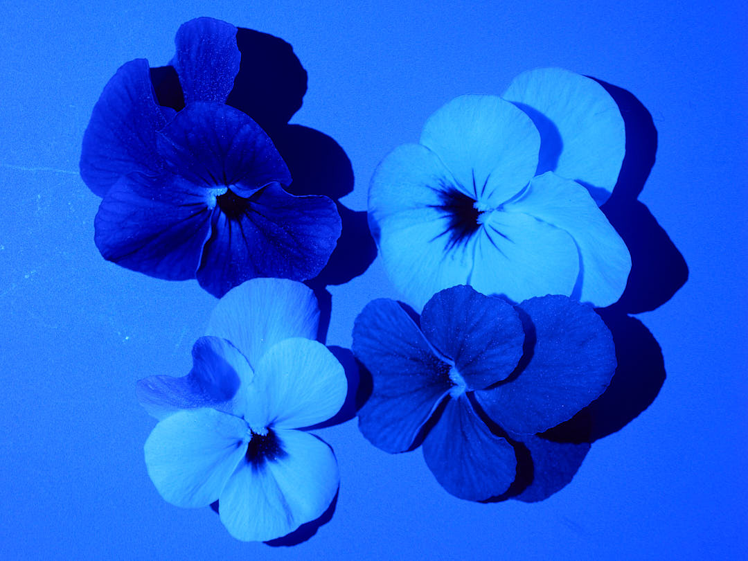
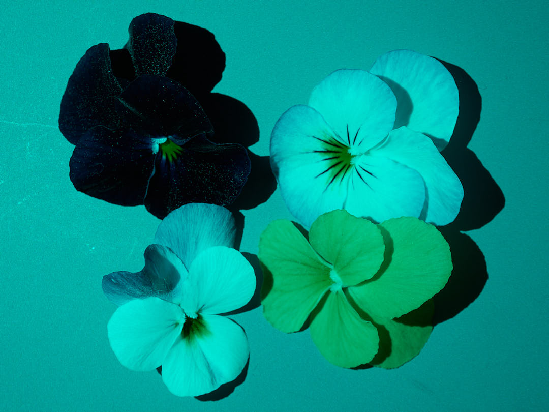
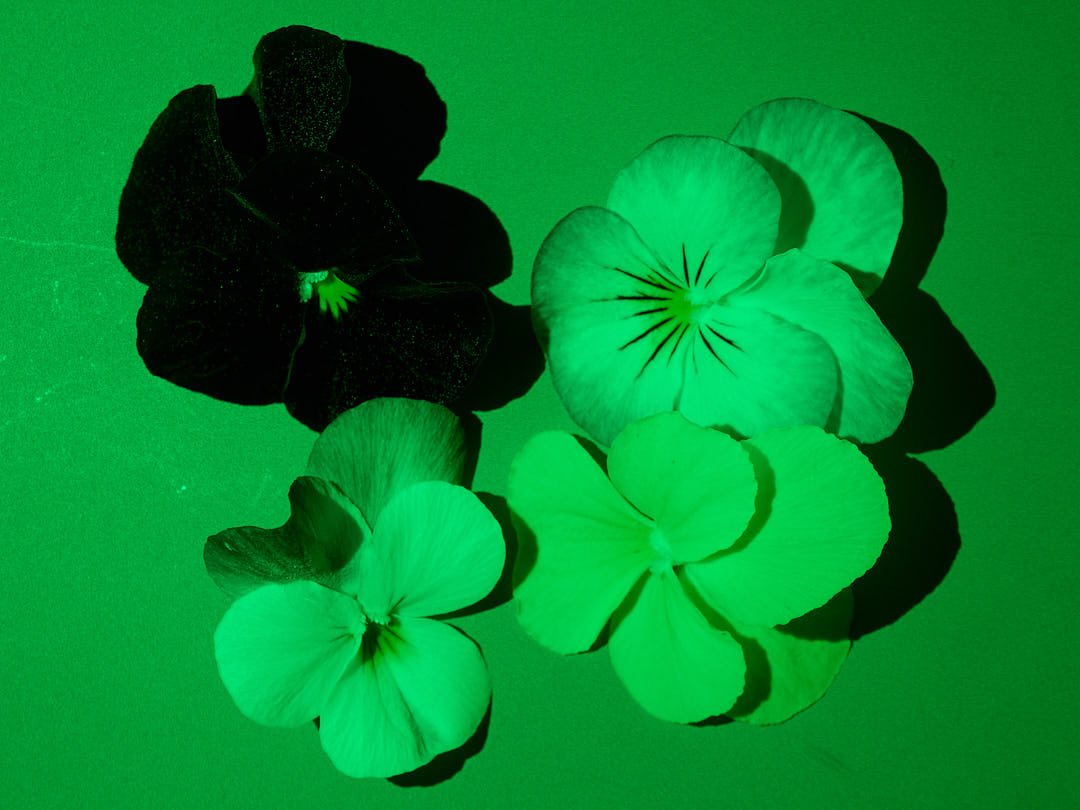
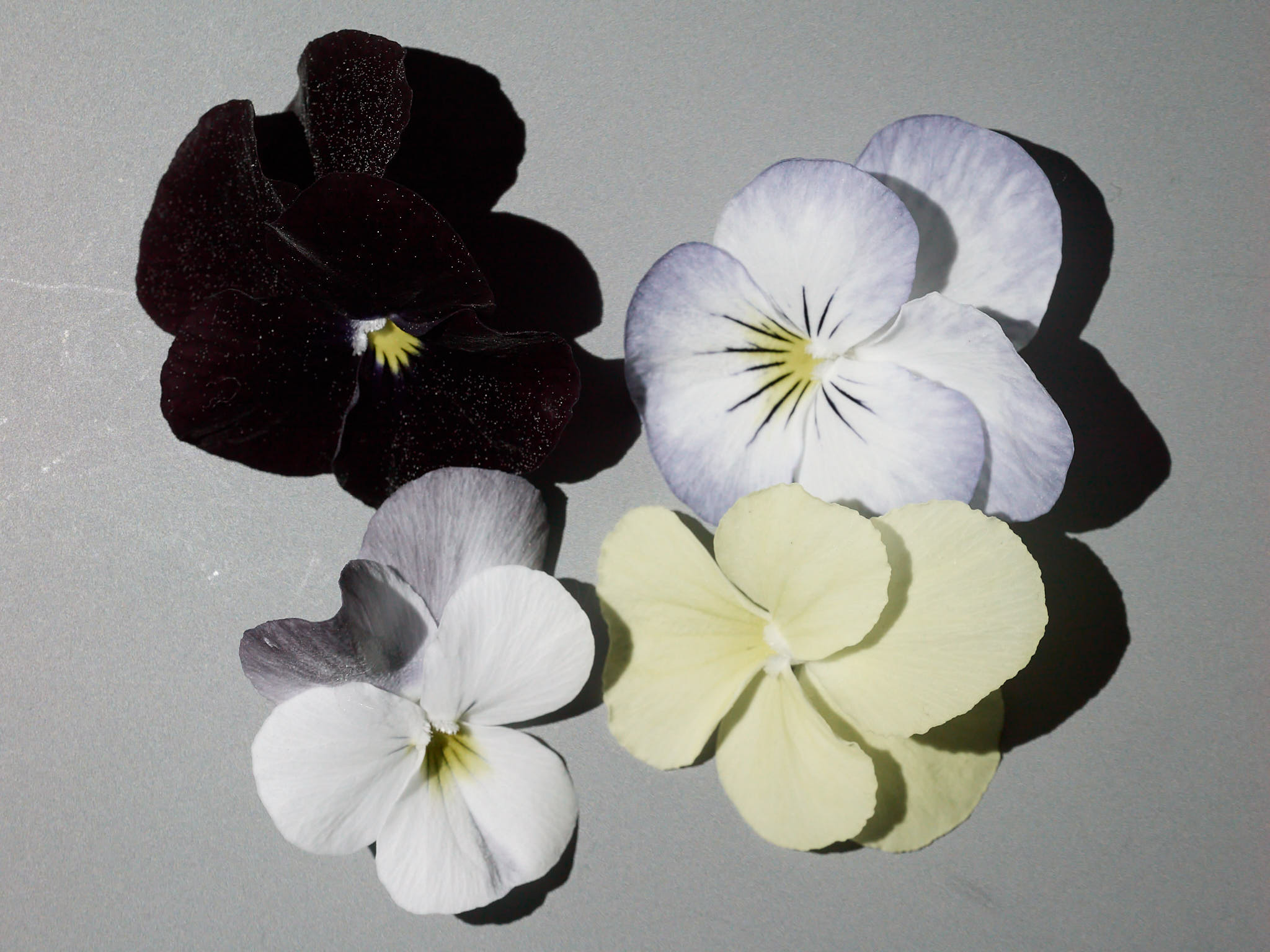
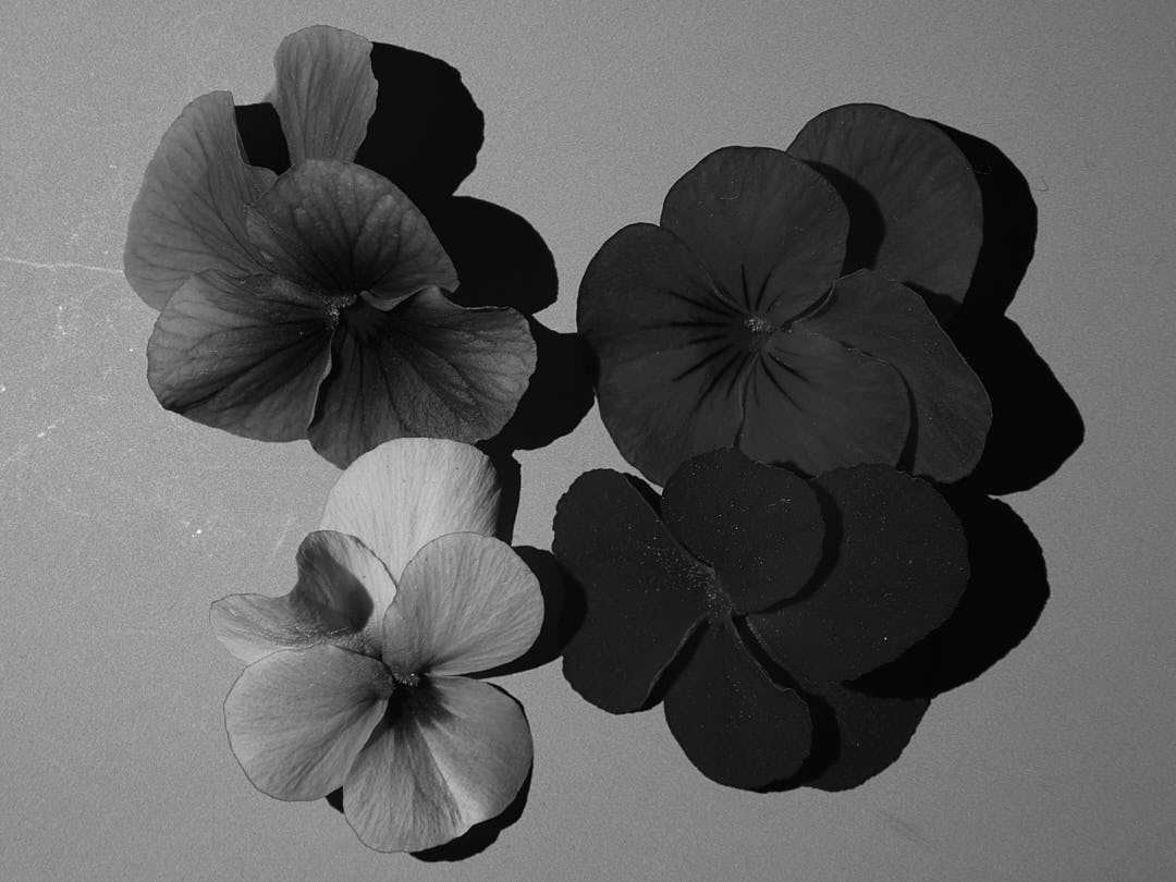
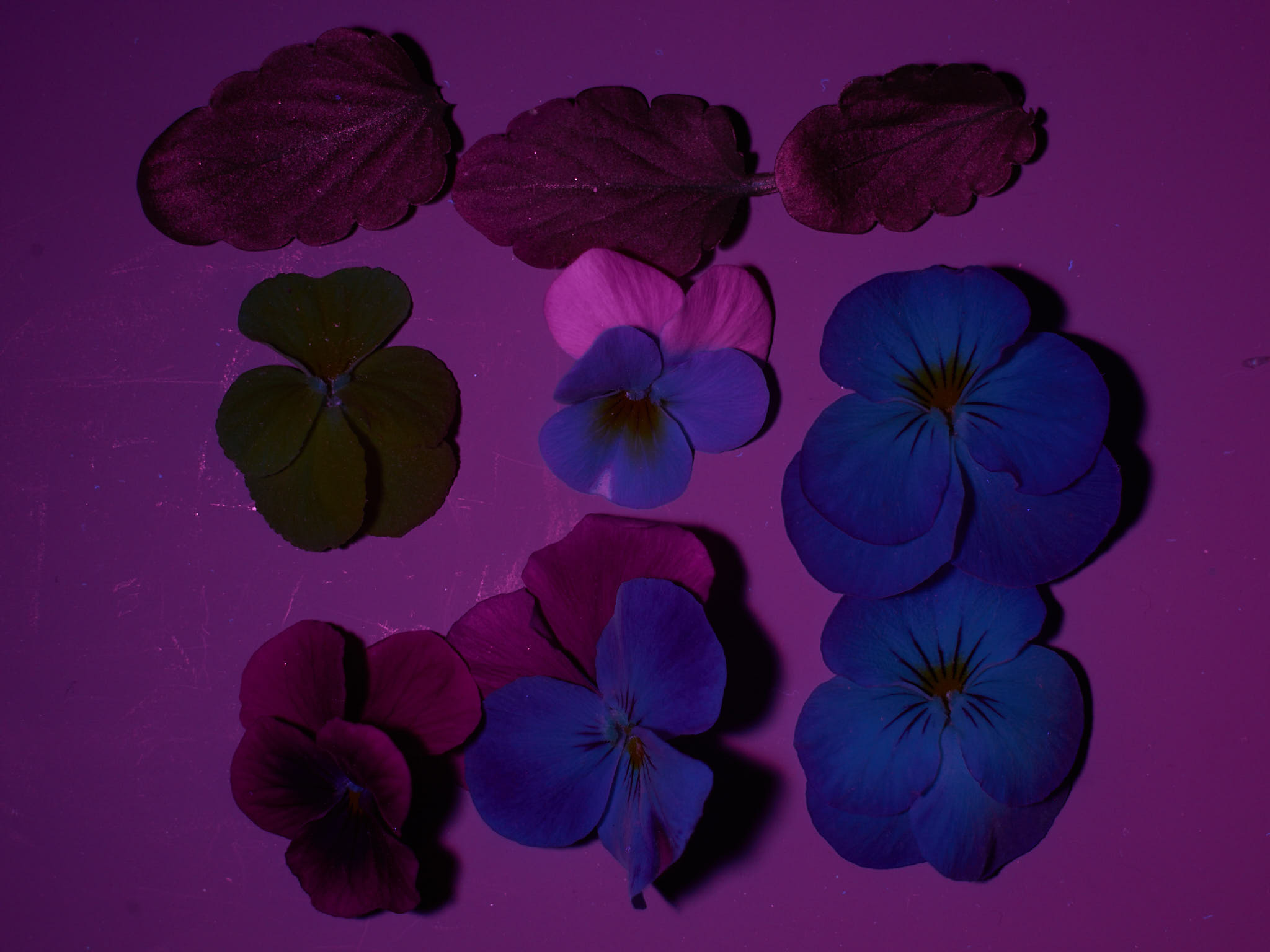
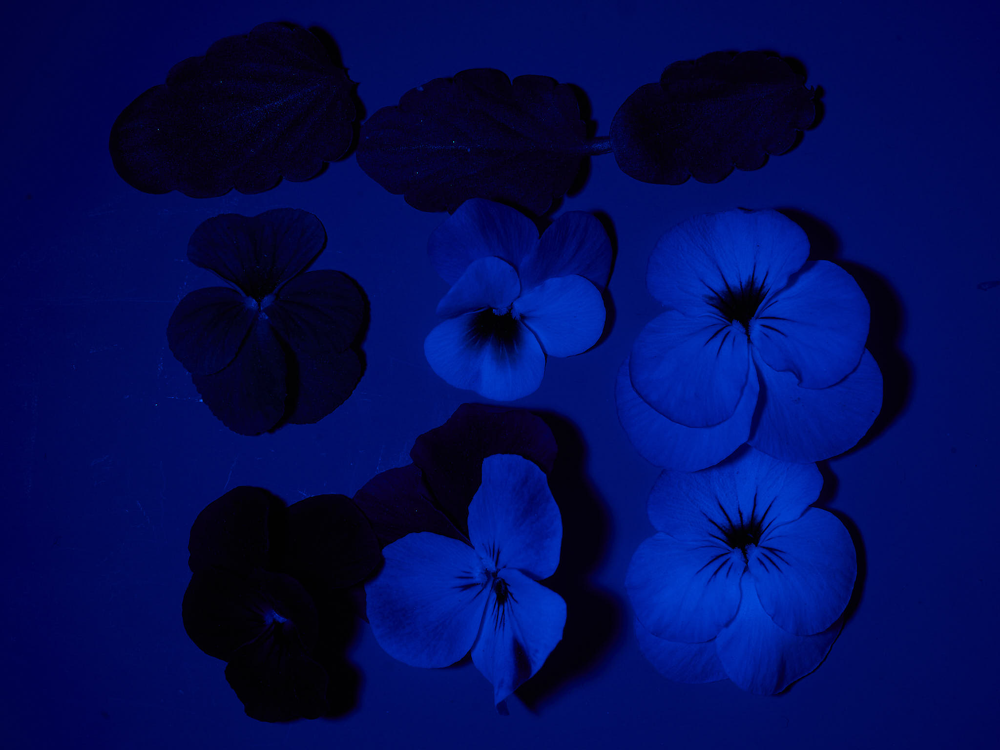
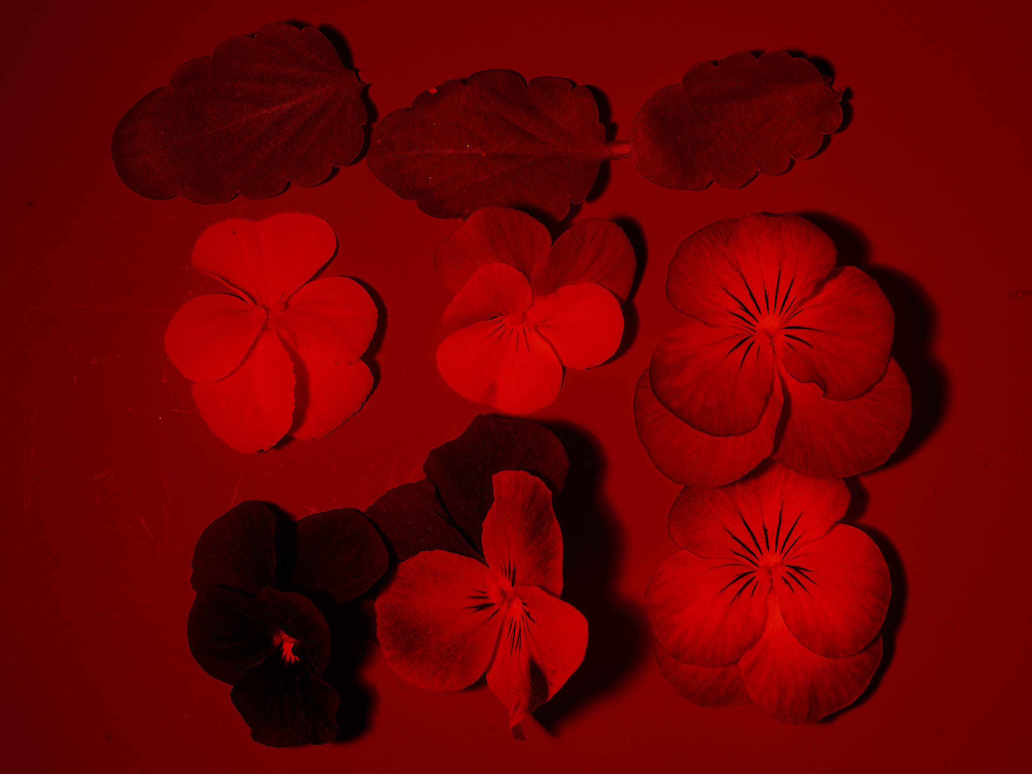
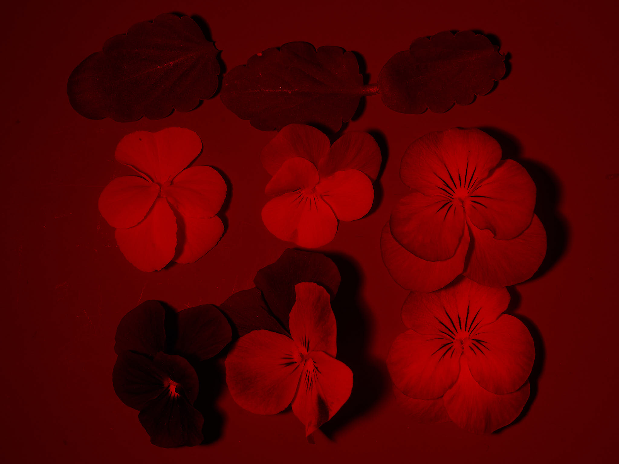
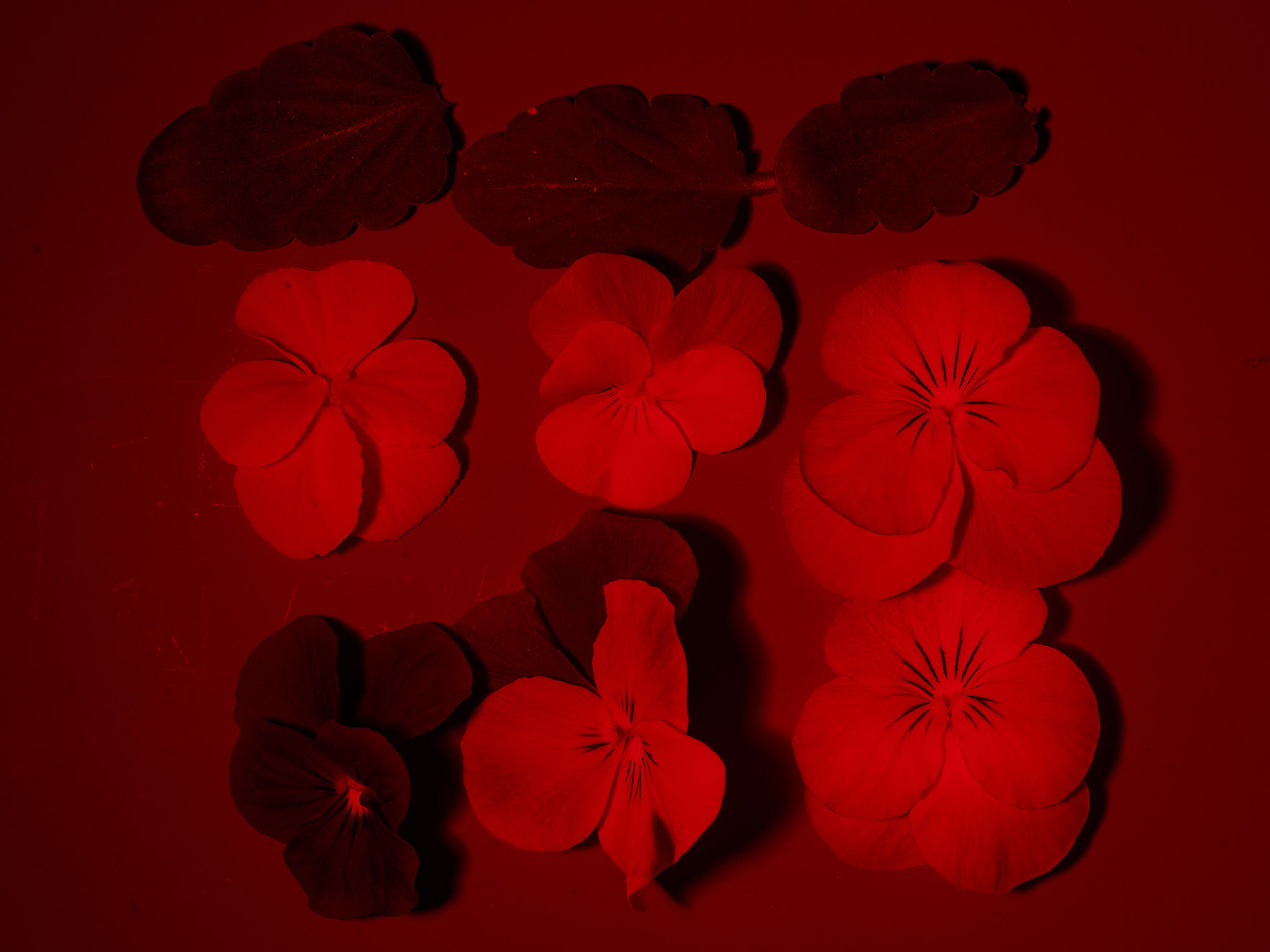
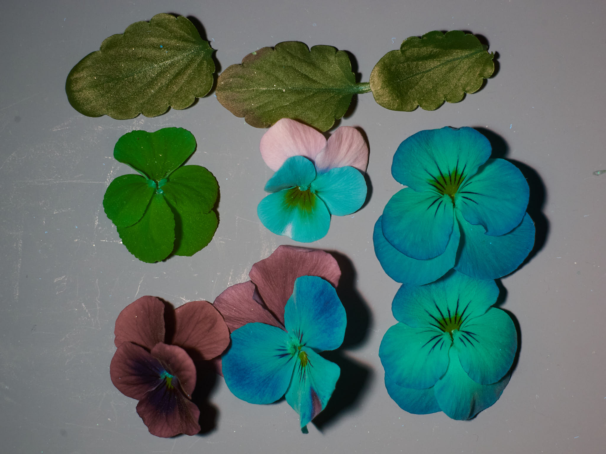
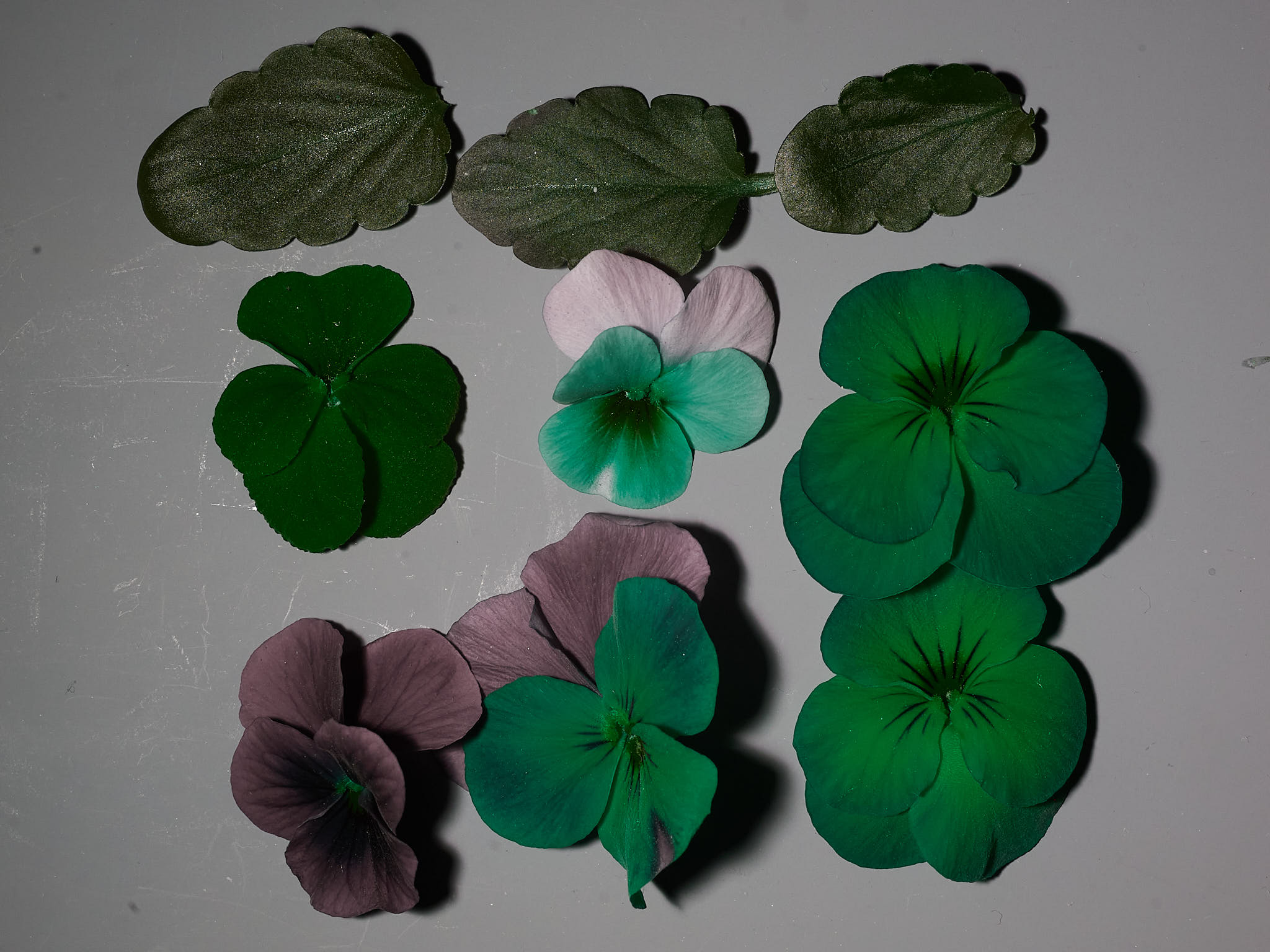
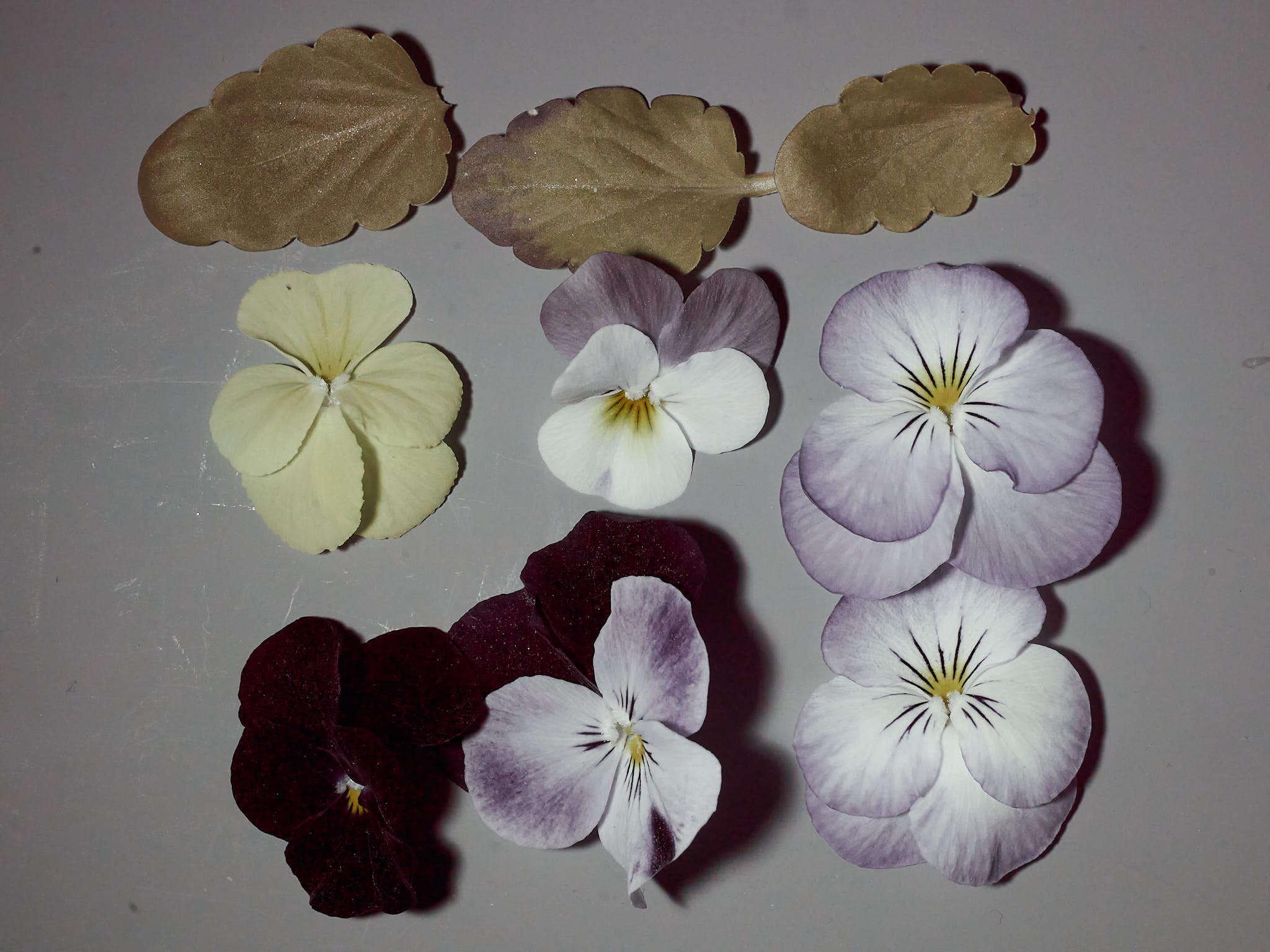
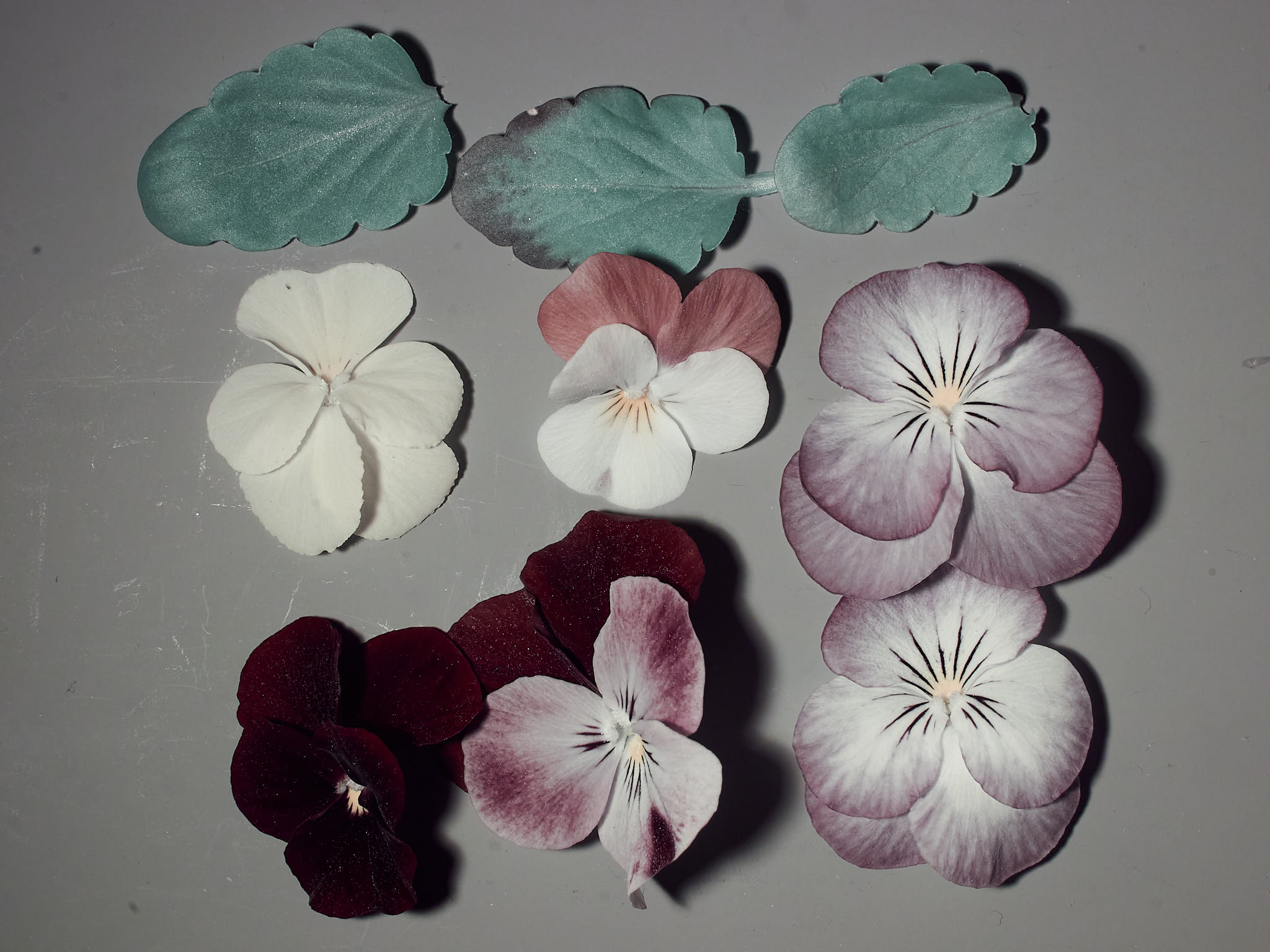
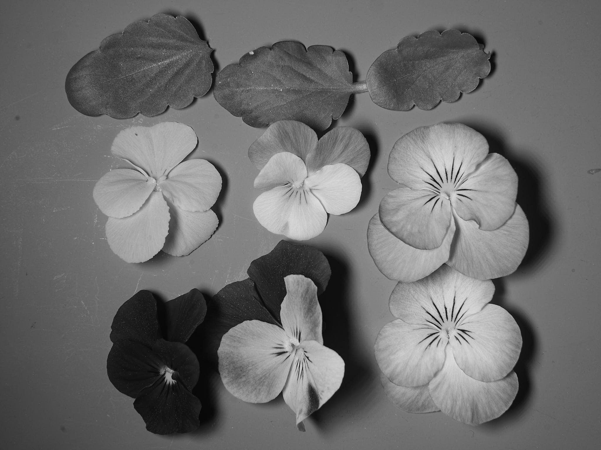
In the images out of the camera the colour of the LED used for illumination predominates (Figure 12).
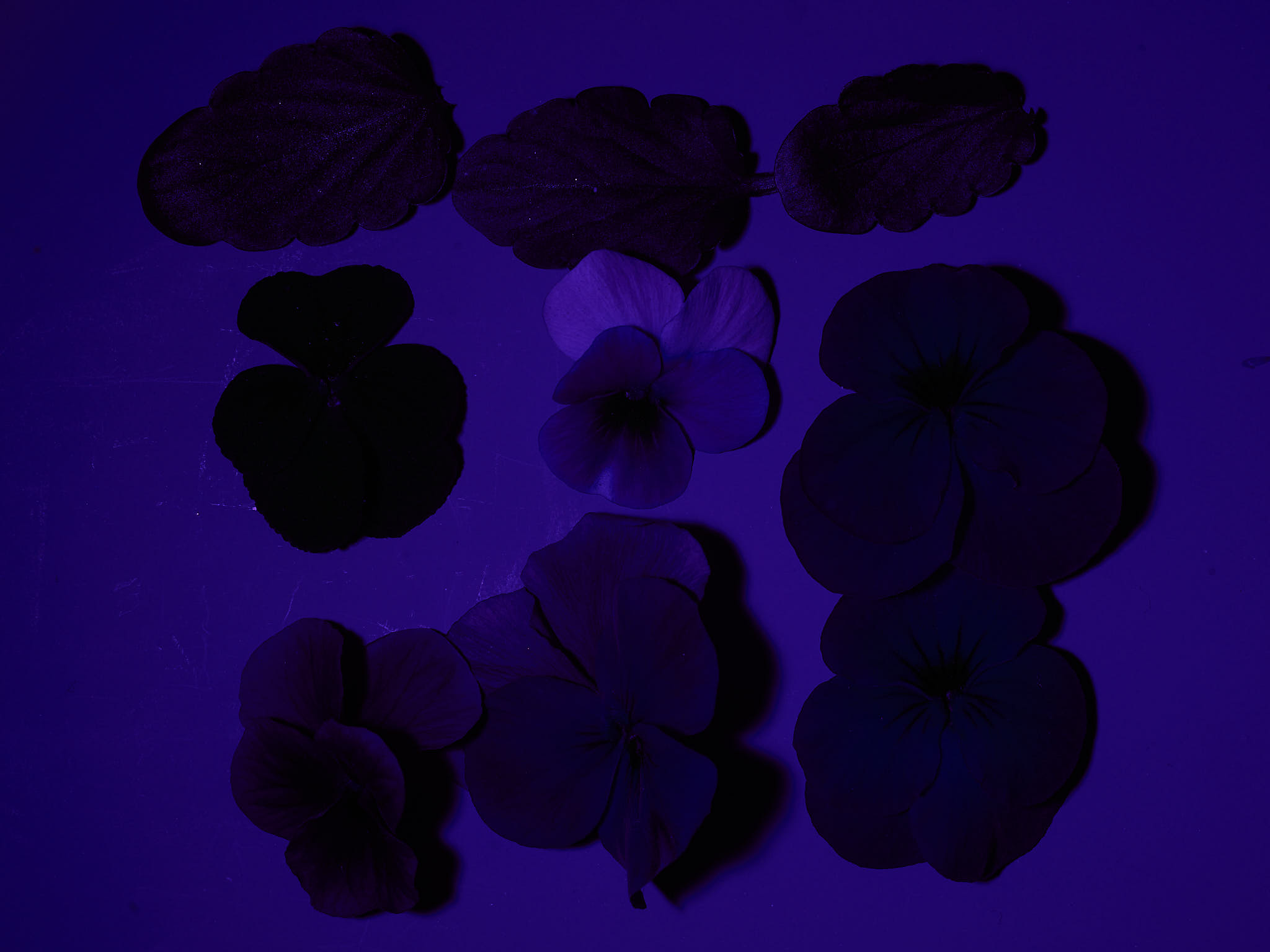
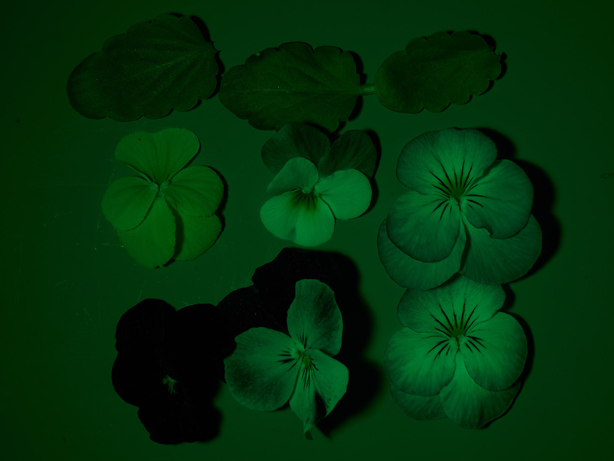
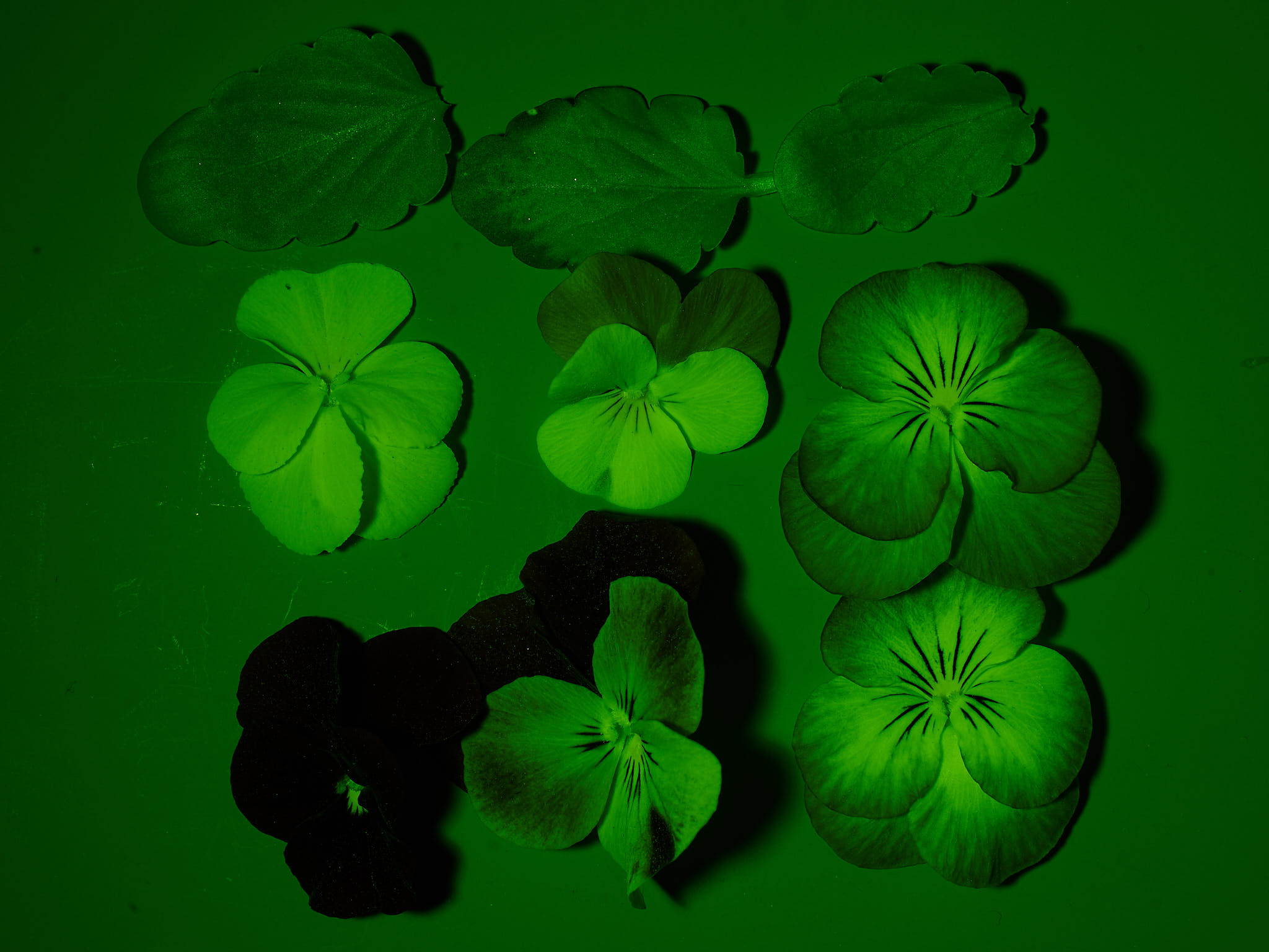
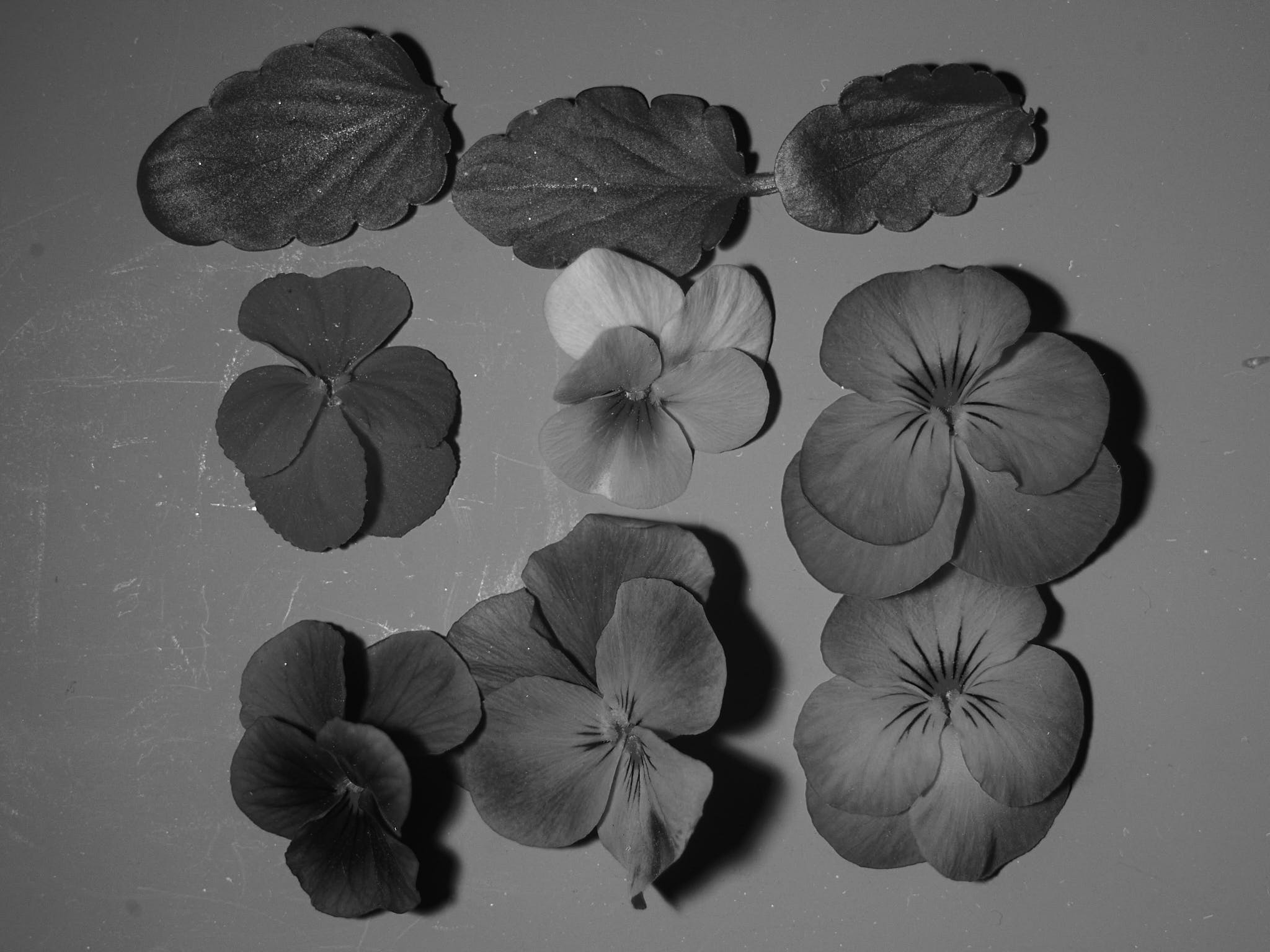
The images above show mainly reflected light. UV-radiation as well as visble light can induce fluorescence in plants. The UV-A1 radiation from the arrays has enough contamination with other wavelengths that even with a UV-blocking filter on the objective the fluorescence cannot be photographed.
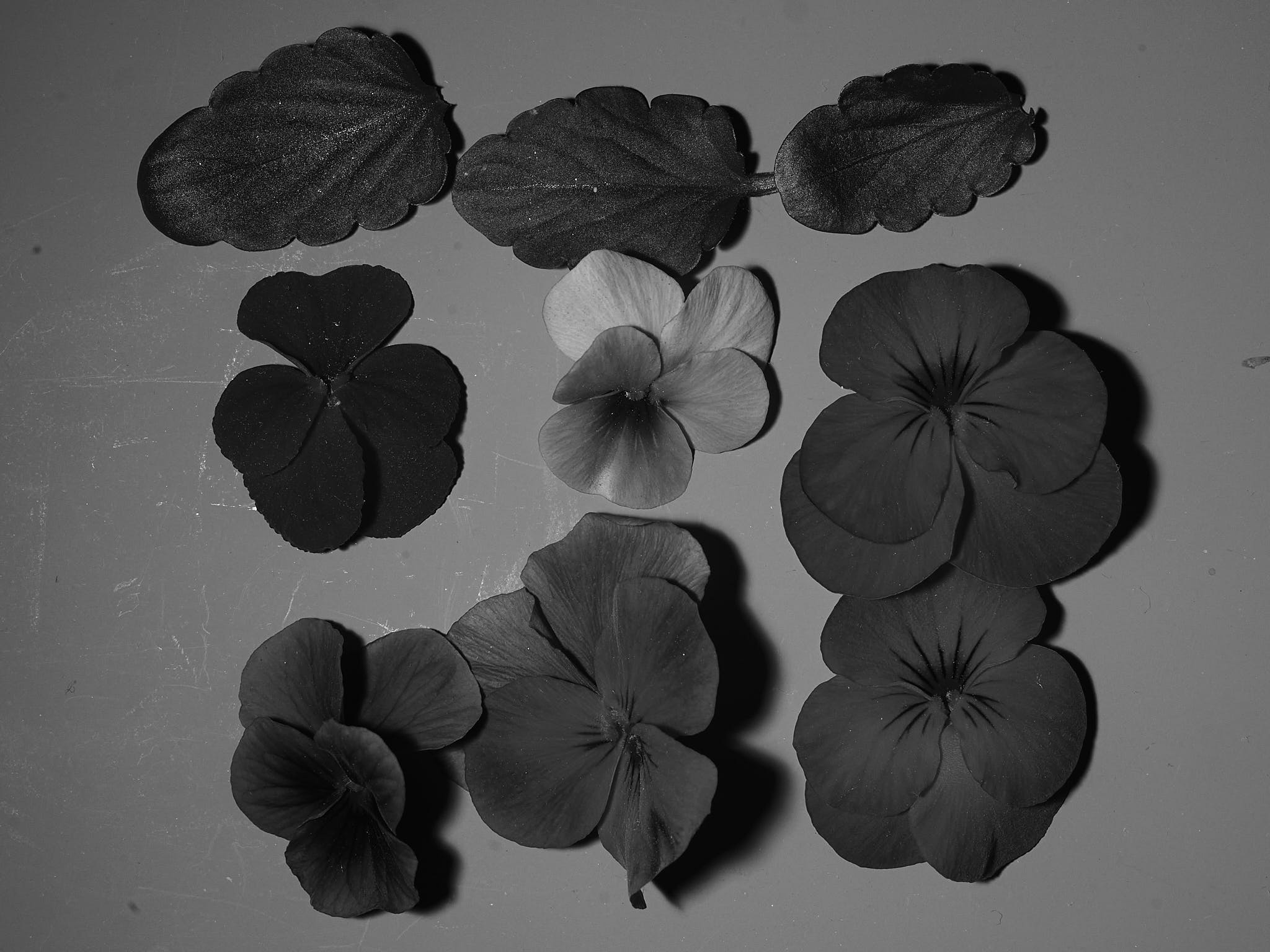
Here I show a photograph of the same set-up of flowers and leaves illuminated with a well-filtered UV-A LED flashlight (Figure 15)