In this page I am compiling some information on custom made and commercial sources of near infrared radiation suitable for photography at relatively close range. This is still a draft of work in progress.
Keywords
LED light, comparison
WarningDangers in flash modification
Bare xenon flash tubes, even if made of glass, emit enough UV-B and UV-A radiation to make it a must to avoid direct exposure or the use of eye protection when used in a darkened or dimly lighted room. It is also possible to adapt xenon flash tubes with a quartz envelope and some flashes may already have such a lamp behind an UV-blocking filter or window. As tubes with a quartz envelope emit strongly in the UV-A, UV-B and UV-C regions all the way down to 250 nm and shorter wavelengths, extreme care should be used to avoid hurting/damaging the subjects photographed as well as the photographer. With quartz xenon tubes the photographer and anybody else exposed to the flash should wear suitable eye and skin protection. As modified digital cameras are not sensitive to UV-C or short UV-B radiation it is most effective and safest to filter out the shorter wavelengths at the flash.
Good eye protection is needed (e.g. with EN170 certification and UV400 rating with no gaps on any sides that could allow either direct or reflected UV ingress), specially if working under conditions where pupils dilate, such as dim red visible light or darkness. Skin exposure at close range should be also avoided.
Modifying a flash should be done only by someone knowledgeable of the risks involved in electronics circuits with lethally high voltages (much higher voltage than mains power and high currents from capacitor discharge) and in the exposure to damaging radiation. If not professionally trained in high voltage electronics and radiation safety, play it safe and get someone else to modify the flash and advice on how to protect yourself from ultraviolet radiation and lethal voltages!
Warning 1: Ultraviolet-A radiation dangers
Ultraviolet-A (UV-A) radiation at high irradiance can be damaging to eyes and skin, especially when there is little or no visible light together with it. Eye protection is recommended in all cases. It is safer to use only the so called “black light” corresponding to UV-A1 at wavelengths near 365 nm. However, even in this case when using flashlights or any other sources of UV-A that emits a concentrated beam, use of safety goggles is a must. When selecting goggles or safety spectacles pay attention to their UV-protection rating (e.g., UV400 CE, or increasing protection from ANSI U2 to U6 markings) as some goggles are certified to protect only from mechanical impacts (e.g., ANSI Z87+ with no U marking) (Figure 1). It is important that goggles and other safety eye wear provide protection also from the sides.
A: In white light.
B: In ultraviolet-A radiation.
Figure 1: Protection eye wear protects the eyes by blocking all UV-A radiation from reaching them. The ones in the photographs are simple ones, given away by an optician to me. They are anyway effective, looking black and casting a dark shadow on the white background. Photographs were taken with a full-spectrum converted Olympus E-M1 camera, using either no filter on the lens and Sunwayfoto FL-96 fill light video lamp or a Jaxman Uc1 UV-A flashlight, and filters ZWB2 stacked with TSN575 on the lens. Lens: Sigma 30 mm 1:2.8 DN MFT. The background was a 5 mm-thick slab of PTFE. A black reference is included in the top-right corner to facilitate consistent editing.
TipFolded code chunks
In this page code chunks can be “folded” so as to decrease the clutter. Above each plot, table or other R-code output you may find one or more “folded” code chunks signalled by a small triangle followed by “Code”. Clicking on the triangle “unfolds” folded chunks making the R code that produced the printed values, plots or tables visible. Clicking on the same icon on an “unfolded” chunk, folds it hiding the code.
The code when visible in the chunks can be copied by clicking on the top right corner, where an icon appears when the mouse cursor hovers over the code listing.
The </> Code drop down menu to the right of the page title makes it possible to unfold and fold all code chunks in the page and to view the Quarto source of the whole web page.
In this page I assume that photographs will be taken with a full-spectrum converted camera using NIR pass filters that block most visble light. A digital camera modified to “see” NIR, a special camera capable of recording NIR (such as the Raspberry Pie NoIR cameras) or IR-sensitive film are a prerequisite to obtaining NIR photographs. The light sources I discuss in this article are too weak to be useful with any digital camera with a built-in NIR blocking filter, i.e., any “normal” digital camera sold for use in visible light.
Even after modification, CMOS sensors in photographic cameras are sensitive up to wavelengths near 1000 nm. The decrease in sensitivity is gradual so there is not clear cut-off. The red, green and blue filters in camera sensors’ Bayer arrays are not selective for wavelengths longer than approximately 850 nm. Greyscale photographs are possible at all wavelengths, but false-colour NIR images require broad illumination in the wavelength range 680 to 800 nm.
Some LED-based flashlights and photography fill lights for “night vision” are commercialy available. All those I know of are based on a single type of LED and emit in a narrow range of NIR wavelengths, either centred at 850 nm or 940 nm. LEDs emitting several other wavelengths of NIR are nowadays also readily available as electronic parts. Different bare LEDs can be assembled into a multi-waveelngth array, but are not easily available ready build.
Xenon flashes do emit NIR in addition to visible light. Their NIR energy emission is as much as in the visible.
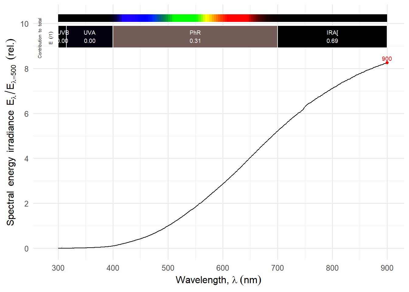
Finally the now difficult to find tungsten halogen incandescent bulbs emit strongly in the NIR but still even more at longer wavelengths.
The notes below are not exhaustive. They are constrained to the few lamps, LEDs and bulbs I have bought over several years.
LED-based commercial lights
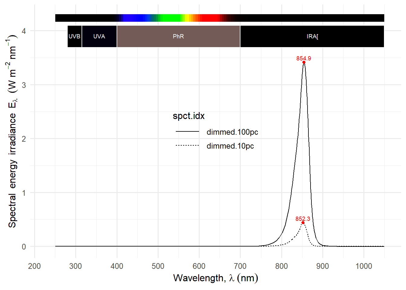
The very cheap (<20 €), Andoer IR49S Mini IR Night Vision Light, with a built-in rechargable lithium battery, has a fully plastic body and no flirs, but implements CC dimming and emits intense NIR over a broad area. Emission is centred at 855 nm shifting very slightly when dimmed (Figure 2 (a)). Nominal power rating is 5 W and the battery has a nominal capacity of 2000mAh. Weight is 95 g. I have bought two of these and they work well. Dimming settings have no obvious steps, the same wheel works as on-off switch and there is no display for the power setting. Consequently, it is difficult to dim it to the same output. The remaining charge in the battery is displayed by four small blue LEDs. This is one out of several very similar “night vision” lights sold at AliExpress under different brand names.
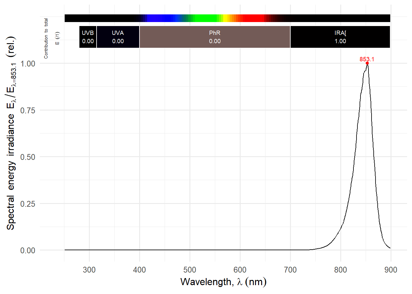
I also have a NIR flashlight with zoom optics powered by a 18659 lithium rechargeable battery. It is a generic one, with no brand marking. The light field is uneven and, thus, less suitable for photography. It could be useful as an aid in focusing when using a flash as NIR source. It’s peak of emission is at 853 nm (Figure 2 (b)).
Figure 2: Emission spectra of two commercially-available LED-based NIR sources.
Xenon flash
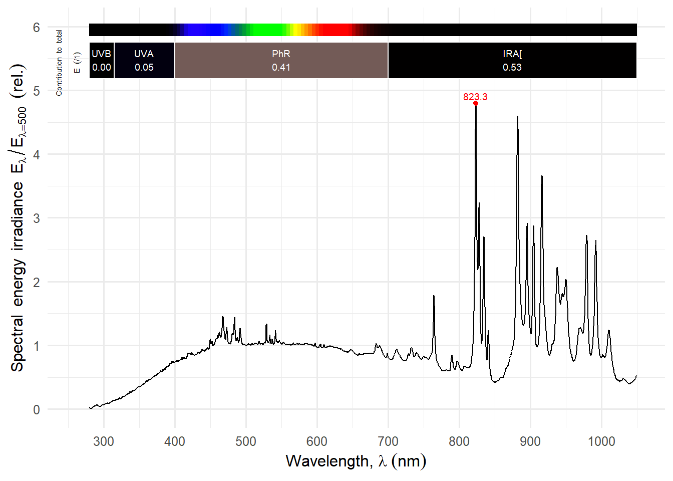
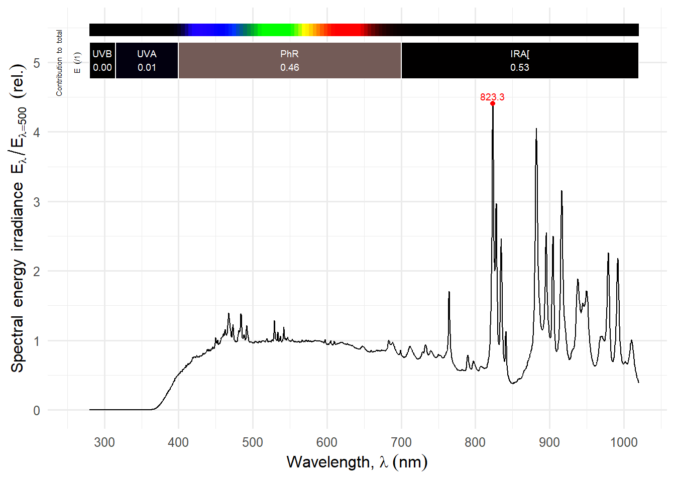
In this section I describe the use of a Godox AD200 flash with a modified H200R head. I have described the flash and its modification in the article Godox AD200 flash for UV, VIS and IR photography at this site. Power settings available go from 1/1 (full power) to 1/128 (minimum power). For the use of the flash in NIR photography there is no need to modify it by removing the built-in UV-absorbing and light diffusing window. It is enough to devise some way of attaching optical filters onto the window. I modified the flash to use it in UV photography.
Code
autoplot(AD200R_power.mspct[-1], by.group =TRUE) +transition_states(spct.idx,transition_length =1,state_length =4) +ggtitle('Power at {closest_state} of maximum')autoplot(AD200R_power.mspct[["1/4"]])autoplot(AD200R_power.mspct[["1/4"]] * filters.mspct$Hoya_UV0_HMC_2.0mm_52mm)
(a) Animation of normalised spectra for different power settings.
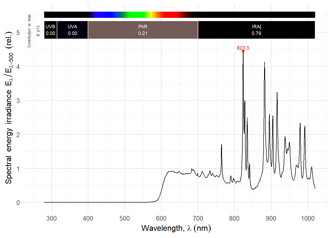
(b) Spectrum at 1/4 power setting.
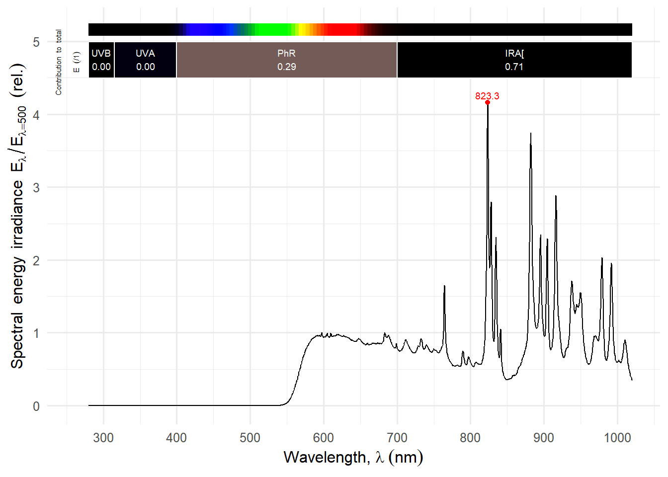
(c) As (b) but filtered with Hoya UV(0).
Figure 3: Spectral emission of the Godox H200R modified flash head for the Godox AD200 flash with no filter or window, and with a UV-blocking filter approximating the spectrum before modification for use in UV photography. Power spectra normalised at 500 nm. The numbers on the bars indicate the fraction of the spectral energy in each region of the spectrum.
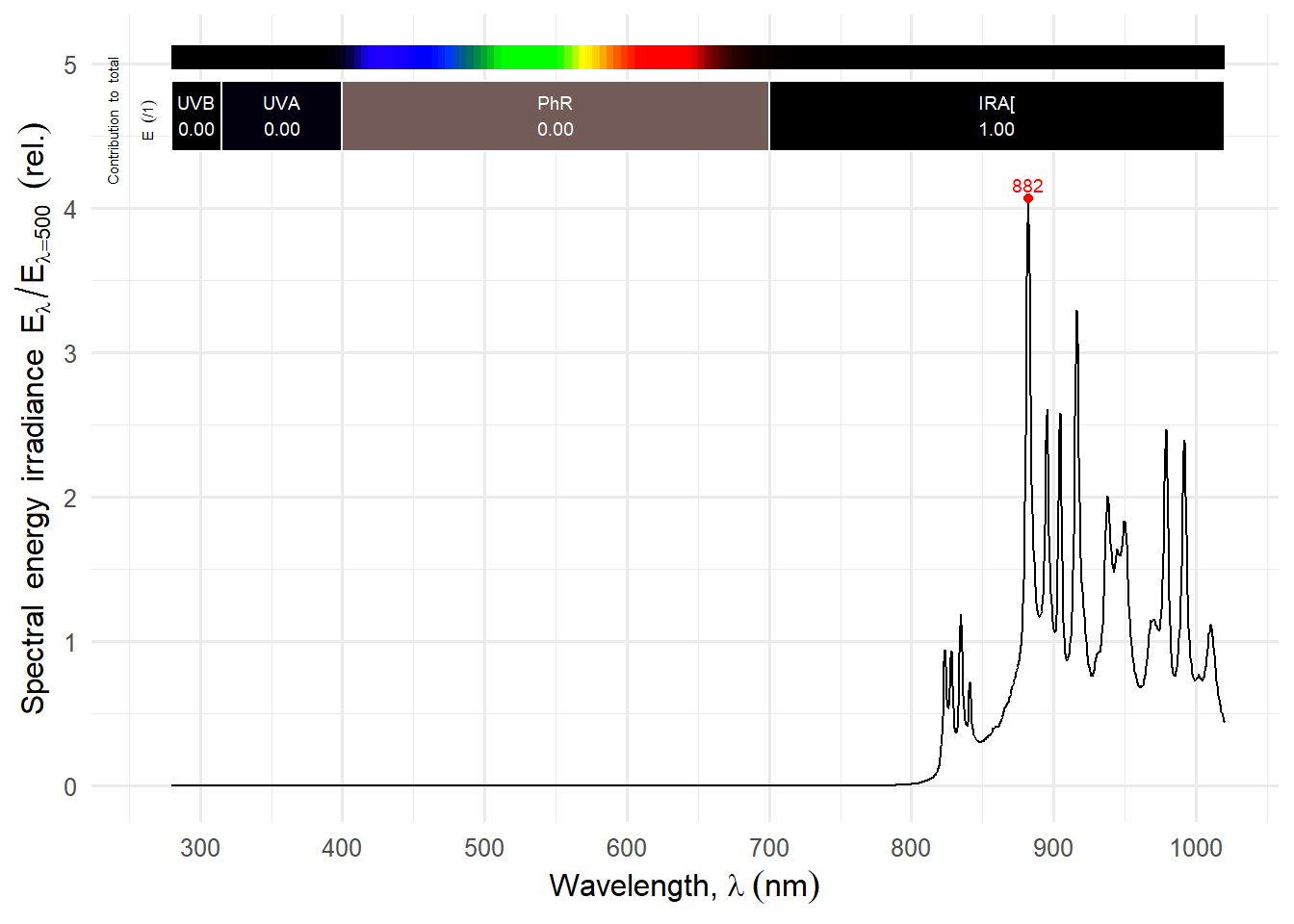
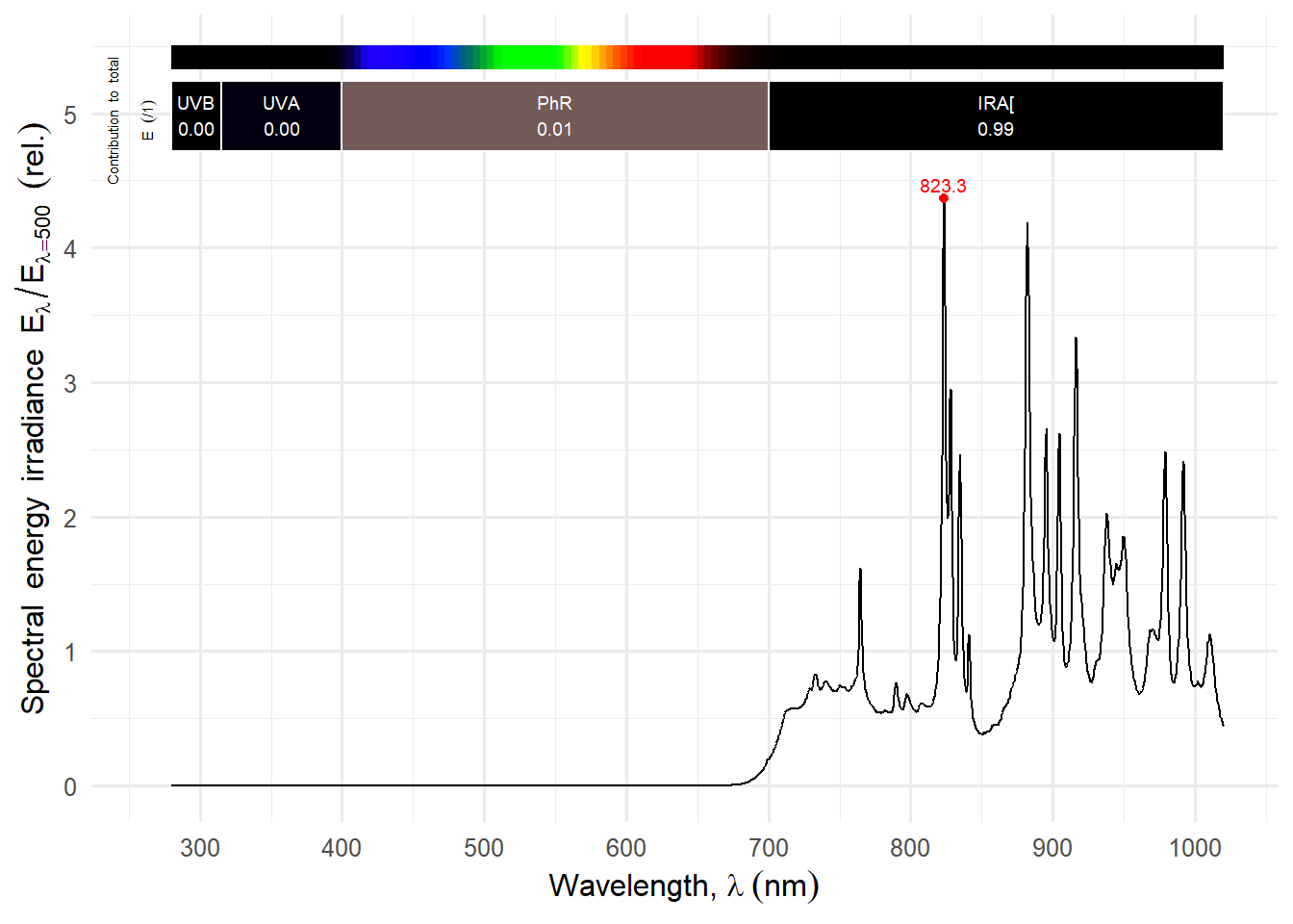
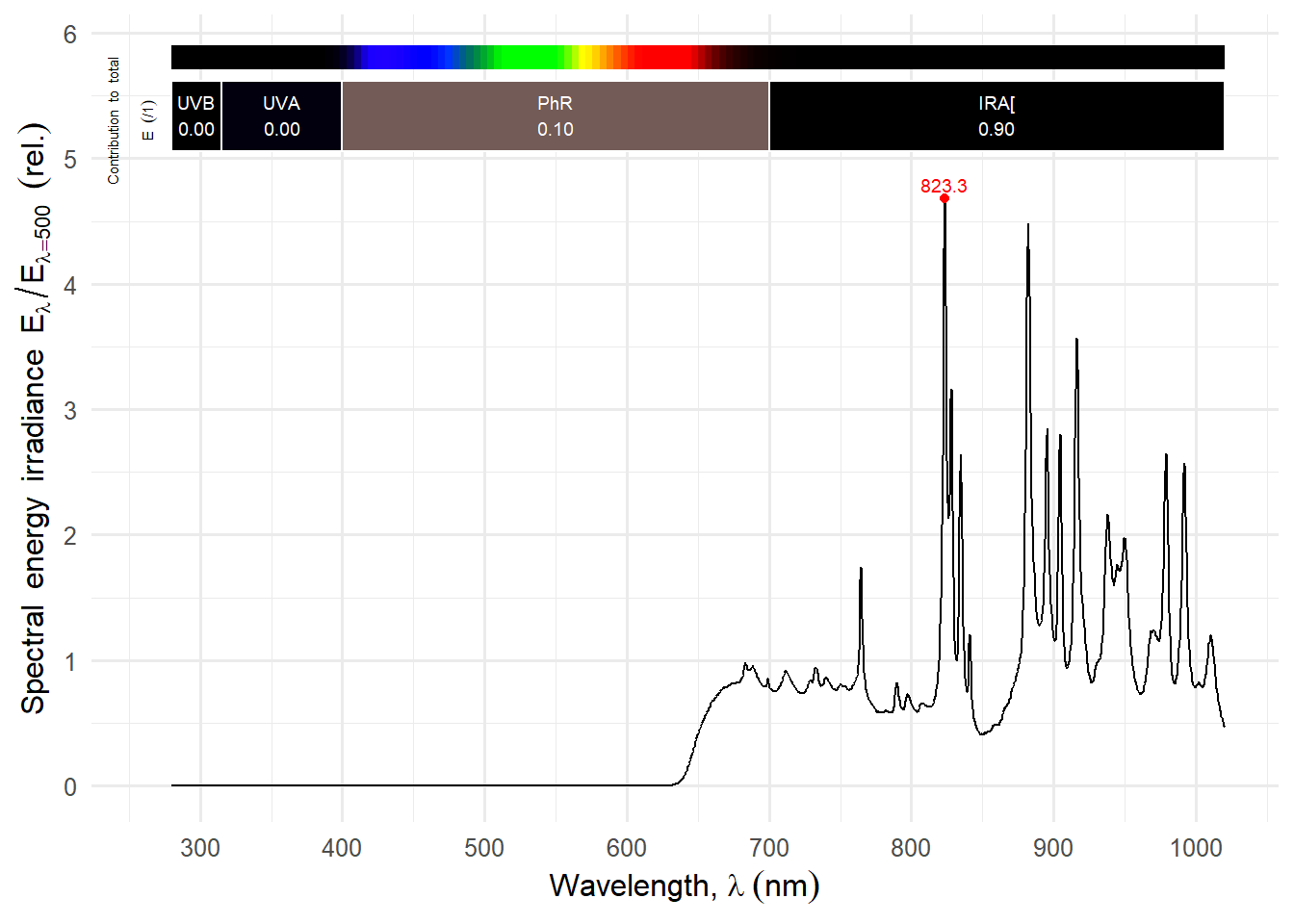
I have modified the round head of the Godox AD200 flash to accept 72 mm (M72) round filters normally used on lenses. Using a NIR-pass, VIS and UV- blocking filter makes it a NIR source for photography with a broad emission spectrum in the NIR region (Figure 4). Contrary to NIR LEDs, the flash can yield NIR photographs with false colour.
Figure 4: Spectral emission of the Godox H200R modified flash head for the Godox AD200 flash when filtered with different NIR-pass filters differeing in their cut-in wavelength. Flash set at 1/4 maximum power, unfiltered power spectrum normalised at 500 nm. Effect of filters computed in silico by convolution of spectra.
---title: "NIR Sources for Photography"subtitle: "LEDs, Xenon flashes and tungsten halogen bulbs"author: "Pedro J. Aphalo"date: "2025-03-07"date-modified: "2025-03-30"toc: truecategories: [equipment, illumination]keywords: [LED light, comparison]format: html: code-fold: true code-tools: true lightbox: autolicense: "CC BY-SA"abstract: | In this page I am compiling some information on custom made and commercial sources of near infrared radiation suitable for photography at relatively close range. This is still a draft of work in progress.draft: false---{{< include /_includes/flash-modification-warning.qmd >}}{{< include /_includes/uva-warning.qmd >}}{{< include /_includes/folded-code-tip.qmd >}}```{r, warning=FALSE, message=FALSE}library(photobiology)library(photobiologyWavebands)library(photobiologyLEDs)library(photobiologyLamps)library(photobiologyFilters)library(ggspectra)library(gganimate)library(patchwork)theme_set(theme_minimal(12) +theme(legend.position ="inside"))options("photobiology.plot.bands"=list(UVB(), UVA(), PhR(), NIR("CIE")))load("data/AD200R-power-mspct.rda")```## IntroductionIn this page I assume that photographs will be taken with a full-spectrum converted camera using NIR pass filters that block most visble light. A digital camera modified to "see" NIR, a special camera capable of recording NIR (such as the Raspberry Pie NoIR cameras) or IR-sensitive film are a prerequisite to obtaining NIR photographs. The light sources I discuss in this article are too weak to be useful with any digital camera with a built-in NIR blocking filter, i.e., any "normal" digital camera sold for use in visible light.Even after modification, CMOS sensors in photographic cameras are sensitive up to wavelengths near 1000 nm. The decrease in sensitivity is gradual so there is not clear cut-off. The red, green and blue filters in camera sensors' Bayer arrays are not selective for wavelengths longer than approximately 850 nm. Greyscale photographs are possible at all wavelengths, but false-colour NIR images require broad illumination in the wavelength range 680 to 800 nm.Some LED-based flashlights and photography fill lights for "night vision" are commercialy available. All those I know of are based on a single type of LED and emit in a narrow range of NIR wavelengths, either centred at 850 nm or 940 nm. LEDs emitting several other wavelengths of NIR are nowadays also readily available as electronic parts. Different bare LEDs can be assembled into a multi-waveelngth array, but are not easily available ready build.Xenon flashes do emit NIR in addition to visible light. Their NIR energy emission is as much as in the visible.Finally the now difficult to find tungsten halogen incandescent bulbs emit strongly in the NIR but still even more at longer wavelengths.The notes below are not exhaustive. They are constrained to the few lamps, LEDs and bulbs I have bought over several years.## LED-based commercial lightsThe very cheap (<20 €), _Andoer IR49S Mini IR Night Vision Light_, with a built-in rechargable lithium battery, has a fully plastic body and no flirs, but implements CC dimming and emits intense NIR over a broad area. Emission is centred at 855 nm shifting very slightly when dimmed ([@fig-andoer-ir49-spct]). Nominal power rating is 5 W and the battery has a nominal capacity of 2000mAh. Weight is 95 g. I have bought two of these and they work well. Dimming settings have no obvious steps, the same wheel works as on-off switch and there is no display for the power setting. Consequently, it is difficult to dim it to the same output. The remaining charge in the battery is displayed by four small blue LEDs. This is one out of several very similar "night vision" lights sold at AliExpress under different brand names.I also have a NIR flashlight with zoom optics powered by a 18659 lithium rechargeable battery. It is a generic one, with no brand marking. The light field is uneven and, thus, less suitable for photography. It could be useful as an aid in focusing when using a flash as NIR source. It's peak of emission is at 853 nm ([@fig-nir-flashligth-spct]).::: {#fig-nir-lamps layout-ncol=1}```{r}#| label: fig-andoer-ir49-spct#| fig-cap: Andoer IR49S Mini IR Night Vision Lightautoplot(andoer_ir49.mspct)``````{r}#| label: fig-nir-flashligth-spct#| fig-cap: Generic NIR zoom flashlightautoplot(lamps.mspct$Generic.LED.NIR.flashlight)```Emission spectra of two commercially-available LED-based NIR sources.:::## Xenon flashIn this section I describe the use of a Godox AD200 flash with a modified H200R head. I have described the flash and its modification in the article [Godox AD200 flash for UV, VIS and IR photography](Godox-AD200.qmd) at this site. Power settings available go from 1/1 (full power) to 1/128 (minimum power). **For the use of the flash in NIR photography there is no need to modify it by removing the built-in UV-absorbing and light diffusing window.** It is enough to devise some way of attaching optical filters onto the window. _I modified the flash to use it in UV photography._::: {#fig-ad200-power layout-ncol=1}```{r}#| label: fig-ad200-power-animation#| fig-cap: Animation of normalised spectra for different power settings.autoplot(AD200R_power.mspct[-1], by.group =TRUE) +transition_states(spct.idx,transition_length =1,state_length =4) +ggtitle('Power at {closest_state} of maximum')``````{r}#| label: fig-ad200-no-filter#| fig-cap: Spectrum at 1/4 power setting.autoplot(AD200R_power.mspct[["1/4"]])``````{r}#| label: fig-ad200-filter-UV#| fig-cap: As (b) but filtered with Hoya UV(0).autoplot(AD200R_power.mspct[["1/4"]] * filters.mspct$Hoya_UV0_HMC_2.0mm_52mm)```Spectral emission of the Godox H200R modified flash head for the Godox AD200 flash with no filter or window, and with a UV-blocking filter approximating the spectrum before modification for use in UV photography. Power spectra normalised at 500 nm. The numbers on the bars indicate the fraction of the spectral energy in each region of the spectrum.:::I have modified the round head of the Godox AD200 flash to accept 72 mm (M72) round filters normally used on lenses. Using a NIR-pass, VIS and UV- blocking filter makes it a NIR source for photography with a broad emission spectrum in the NIR region ([@fig-ad200-with-filters]). Contrary to NIR LEDs, the flash can yield NIR photographs with false colour.::: {#fig-ad200-with-filters layout-ncol=1}```{r}#| label: fig-ad200-850#| fig-cap: Filtered by Zomei IR850autoplot(AD200R_power.mspct[["1/4"]] * filters.mspct$Zomei_IR850_2.0mm_72mm)``````{r}#| label: fig-ad200-720#| fig-cap: Filtered by Zomei IR720autoplot(AD200R_power.mspct[["1/4"]] * filters.mspct$Zomei_IR720_2.0mm_72mm)``````{r}#| label: fig-ad200-695#| fig-cap: Filtered by RG695autoplot(AD200R_power.mspct[["1/4"]] * filters.mspct$Heliopan_RG695_2.2mm_52mm)``````{r}#| label: fig-ad200-665#| fig-cap: Filtered by RG6665autoplot(AD200R_power.mspct[["1/4"]] * filters.mspct$Heliopan_RG665_2.3mm_46mm)``````{r}#| label: fig-ad200-600#| fig-cap: Filtered by Hoya 25Aautoplot(AD200R_power.mspct[["1/4"]] * filters.mspct$Hoya_25A_HMC_2.3mm_52mm)``````{r}#| label: fig-ad200-570#| fig-cap: Filtered by Heliopan 22autoplot(AD200R_power.mspct[["1/4"]] * filters.mspct$Heliopan_Orange_22_SH_PMC_2.2mm_52mm)```Spectral emission of the Godox H200R modified flash head for the Godox AD200 flash when filtered with different NIR-pass filters differeing in their cut-in wavelength. Flash set at 1/4 maximum power, unfiltered power spectrum normalised at 500 nm. Effect of filters computed in silico by convolution of spectra.:::## Incandescent lamps```{r}#| label: fig-tungsten-60W#| fig-cap: Incandescent lamp, 60W.autoplot(normalise(setNormalised(lamps.mspct$Generic.Inc.bulb.60W), norm =500))```## Conclusion